321
AC POWER
DC FUSE
FUSE INSIDE
Fuse Rating
T40AL 32V
REMOTE
DC POWER
24V 40A
AC 230V /50Hz
LOW
IMP
HIGH
IMP
4
3
2
1
56
NIGHT
RINGER
PAGING
IN
TEL
MESSAGE
FIRST
PRIORITY
ATT. OUTPUTS
SPK ZONES
4 100V
FD-21
Pilottone-Module
FS-40
Frequency Shift-Module
FM-30
DC/AC/FAN
Error Monitoring-Module
EACH ZONE / (MAX)
Remote
Receiver
Remote
Receiver
RR-60RR-60
40
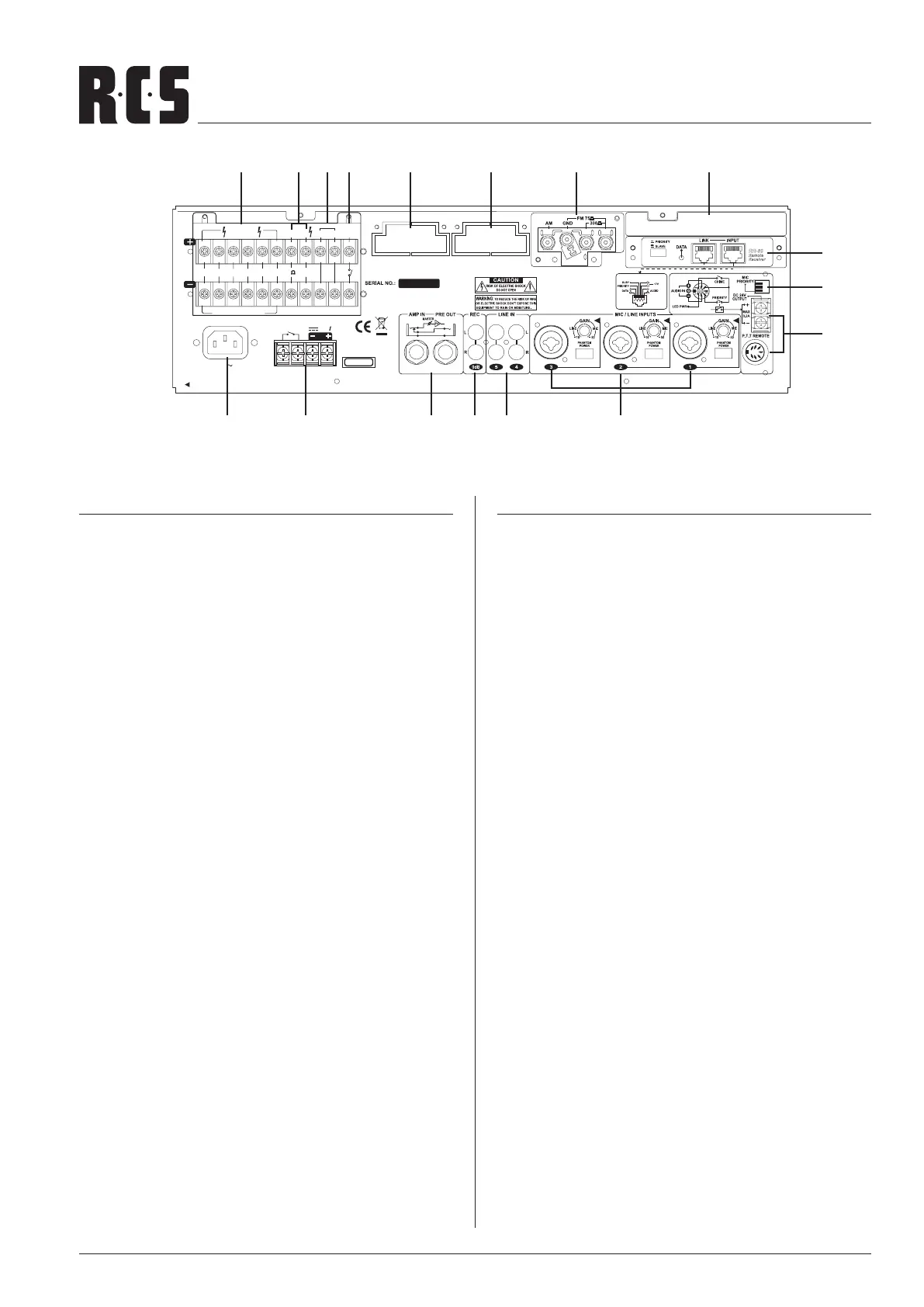
RÜCKANSICHT VLZ-SERIE
1. MIC PRIORITY Schalter
3-fach Schalter um die Priorität der Mikrophoneingänge
1 bis 3 zu aktivieren. MIC 1 - 3 können separat auf "on"
(Priorität) gestellt werden. Dadurch wird Priorität gegen-
über den LINE Eingängen 4, 5, Night Ringer, Sirene und
allen Modulen (außer DM-10) erreicht, vorrausgesetzt der
Jumper MS 2 steht auf "SLAVE".
2. P.T.T REMOTE
7-polige DIN-Buchse für P.T.T Mikrophon (VLM-100) und
24V Ausgang. Damit können 24V Pichtrufrelais geschal-
tet werden. Die 24V liegen an, wenn die Priorität der Mi-
krophon-Sprechstelle VLM-100 aktiviert ist und betätigt
wird.
Für Mikrophonsprechstelle-VLM-100 "Phantom Power"
einschalten und Gain-Regler Eingang 1 auf MIC-Position
drehen.
3. MIC / LINE INPUTS
Drei symmetrische MIC/LINE-Eingänge auf Combo-Buch-
sen (XLR und Klinke). Je 1 Gain Regler von -10dB (LINE) bis
-50 dB (MIC).
Tastschalter für "Phantom Power" (Kondensatormikro-
phon). Für jeden MIC / LINE Eingang ist ein separater
Tastschalter für "Phantom Power" vorhanden.
4. LINE-IN 4 & 5
Die Eingänge 4 und 5 (L + R, unsymmetrische Cinch-
buchsen) sind zum Einschleifen von CD-Player, Kasset-
ten-Deck, o.ä. vorgesehen.
5. REC OUTPUT
Recording output auf Cinchbuchsen, unsymmetrisch,
0dB. Hiermit können alle eingespeisten Signale aufge-
zeichnet werden. Die Lautstärkeregelung erfolgt dabei
über den Regler welcher dem eingespeisten Signal zuge-
ordnet ist, nicht über den "MASTER" Regler.
REAR VIEW VLZ-SERIES
1. MIC PRIORITY SWITCH
Triple switches to activate the priority of the microphone
input 1 to 3. MIC 1 - 3 can be switched separately to “on”
(priority). Because of that and if the Jumper MS 2 is swit-
ched to “SLAVE”, priority is reached opposite of the LINE
inputs 4 and 5, Night Ringer, Siren and all modules (ex-
cept DM-10).
2. P.T.T REMOTE JACK (DIN 7 PIN)
The 7-pin DIN connector connecting P.T.T Remote
(VLM-100) and 24V Output, to switched the 24V
obligation call relays. The 24V connected, if the priority
of the microphone station VLM-100 is activated and one
operates.
Switch to "Phantom Power" for microphone station
VLM-100. Turn the Gain control input 1 to MIC position.
3. MIC / LINE INPUT
Three MIC/LINE-Inuts with gain control on balanced
combo sockets (XLR and jack). Variable range of input
gain is -10dB to -50dB.
Push-button for "Phantom Power" (condenser micropho-
ne). For each MIC/LINE input is a separate push-button
for “phantom power” available.
4. LINE-IN 4 & 5
The input 4 and 5 (L + R, unbalanced jack plugs) are used
for the connection of line-level equipment such as tape
decks, CD-players, or similar.
5. REC OUTPUT
Recording output designed with two unbalanced (0dB)
jack plugs. All signals can be recorded but recording
out can not be adjusted by master volume because re-
cording output is in the front of circuit of master volume
control.
G J
CD
H I Q O M
N
P
A
B
EFKL
REAR PANEL VLZ-SERIES
 Loading...