PILOTTONE-MODULE FD-21
The fault detecting module is available as
an accessory and is not supplied with the
amplier.
It is inserted instead of the cover plate
(see rear view no.
Q).
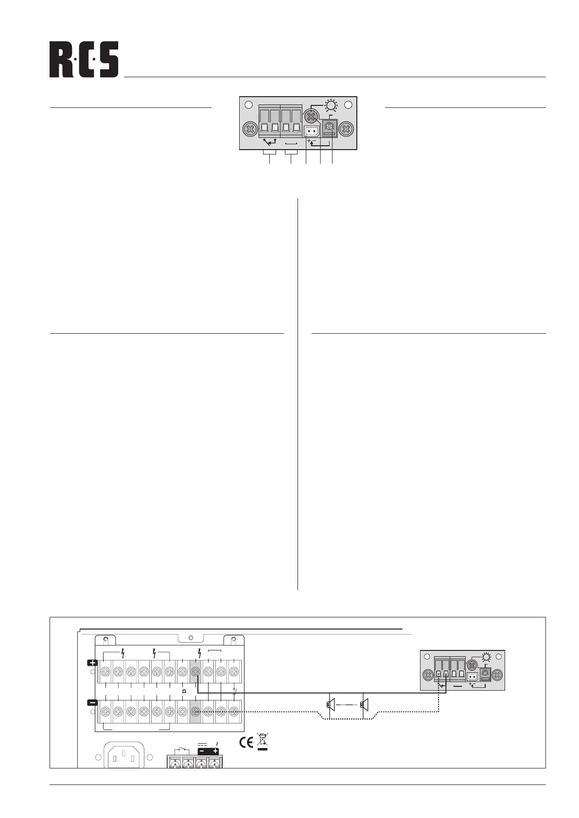
1. Relay output forconnectionofasignaldevice
2. Connections COM and HOT;
tobeconnectedtotheconnectionsHIGHIMP(seerear
viewno.
8):COMatB,HOTatA
3. Measuring points foradjustingtheresponsesensitivity.
2. Control for the 20 kHz test tone level.
5. Control for the response sensitivity.
FD-21 INSTALLATION STEPS:
1. Disconnect the amplier from the mains and from the
emergency power supply.
2. Screw off the housing cover of the amplier and remove
the cover plate
Q.
3. Insert the module PA-6FD from the outside at the place
of the cover plate and screw it tightly.
4. Connect the 5-pole line (B) of the amplier to the jack
CN 601 of the module (see layout plan page 11).
5. Connect the negative contact of the connection HIGH
IMP at the amplier to the contact COM of the screw ter-
minal Line In
b at the module and the positive contact
of HIGH IMP to the contact HOT of Line In.
6. Connect the jumper SW 1 on the monitoring module to
position ON.
7. If a fault is recognized by the module, the LED FAULT
lights up and the relay contacts
a close. For alarm trig-
gering, a signal device may be connected to the con-
tacts. The rating of the relay contacts is 1 A at 120 V~
max. or 24 V max.
Fault Detector
COM HOT
Line In
Test
RMS 2Vac
Sensitivity
maxmin
OSC Level
FD-21
a b c ed
Fault Detector
COM HOT
Line In
Test
RMS 2Vac
Sensitivity
maxmin
OSC Level
FD-21
AC POWER
DC FUSE
FUSE INSIDE
Fuse Rating
T40AL 32V
REMOTE
DC POWER
24V40A
AC 230V /50Hz
1420W
LOW
IMP
HIGH
IMP
4
3
2
1
56
NIGHT
RINGER
PAGING
IN
TEL
MESSAGE
FIRST
PRIORITY
ATT. OUTPUTS
SPK ZONES
4 100V
EACH ZONE / 80W(MAX)
40
LAUD SPEAKERS
PILOTTON-MODUL FD-21
Das Fehlerüberwachungsmodul ist als
Zubehör erhältlich und gehört nicht zum
Lieferumfang des Verstärkers.
Es wird anstelle des Abdeckbleches
(s. Rückansicht Nr.
Q) eingesetzt.
1. Relaisausgang zumAnschlusseinesSignalgebers.
2. Anschlüsse COM und HOT;
mitdenAnschlüssenHIGHIMP(s.RückansichtNr.
8)
verbinden:COMan
B,HOTanA.
3. Messpunkte zum Einstellen der Ansprechempndlichkeit.
4. Regler für den 20-kHz-Testtonpegel.
5. Regler für die Ansprechempfindlichkeit.
FD-21 INSTALLATIONS SCHRITTE:
1. Den Verstärker vom Netz und von der Notstromversor-
gung trennen.
2. Den Gehäusedeckel des Verstärkers abschrauben und
das Abdeckblech
Q am Verstärker entfernen.
3. Das Modul FD-21 an der Stelle des Abdeckblechs von
außen einsetzen und festschrauben.
4. Die 5-polige Leitung (B) des Verstärkers in die Buchse
CN 601 des Moduls stecken (s. Anschlußplan Seite 11).
5. Den Minuskontakt des Anschlusses HIGH IMP am Verstär-
ker mit dem Kontakt COM der Schraubklemme LINE IN
b am Modul verbinden und den Pluskontakt von HIGH
IMP mit dem Kontakt HOT von LINE IN.
6. Die Steckbrücke SW 1 auf dem Überwachungsmodul in
die Position ON stecken.
7. Wird von dem Modul ein Fehler erkannt, leuchtet die An-
zeige FAULT am Verstärker und die Relaiskontakte
a
schließen. An die Kontakte lässt sich zur Alarmierung ein
Signalgeber anschließen. Die Belastbarkeit der Relais-
kontakte beträgt 1 A bei max. 120 V~ oder max. 24 V .
(optional) MODULE FD-21 VLZ-SERIES
 Loading...