(optional) MODULE FM-30 VLZ-SERIES
FEHLER MONITORING-MODUL
FM-30
Das Fehlermeldemodul ist als Zubehör
erhältlich und gehört nicht zum Liefer-
umfang des Verstärkers.
Es wird anstelle des Abdeckbleches
O eingesetzt.
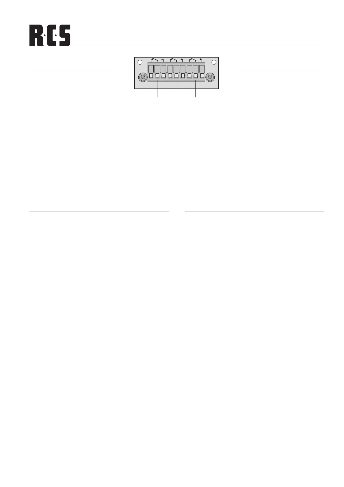
Relaisausgänge zum Anschluss von Signalgebern:
1. Relais AC sprichtan,wennkeineNetzspannunganliegt,
die interne Netzsicherung durchgeschmolzen ist oder
derNetzschalternichtaufONsteht.
2. Relais DC spricht an, wenn die Sicherung für die
Notstromversorgung durchgeschmolzen ist oder keine
Spannung von einer Notstromeinheit an den Anschlüs-
senDCPOWERanliegt.
3. Relais FAN spricht an, wenn der interne Lüfter defekt
oder nicht angeschlossen ist.
FM-30 INSTALLATIONS SCHRITTE:
1. Den Verstärker vom Netz und von der Notstromversor-
gung trennen.
2. Den Gehäusedeckel des Verstärkers abschrauben und
das Abdeckblech entfernen.
3. Das Modul FM-30 an der Stelle des Abdeckblechs von
außen einsetzen und festschrauben.
4. Die 6-polige Leitung (C) des Verstärkers in die Buchse
CN 5 des Moduls stecken (s. Anschlußplan Seite 11).
5. Die Signalgeber zur Alarmierung an die Relaisumschalt-
kontakte
a, b oder c anschließen.
Der Aufdruck am Modul zeigt die Kontaktstellung im Feh-
lerfall und bei ausgeschaltetem Verstärker. Die Belastbar-
keit der Relaiskontakte beträgt 1 A bei max. 120 V~ oder
max. 24 V .
ERROR MONITORING MODULE
FM-30
The fault monitoring module is availa-
ble as an accessory and is not sup-
plied with the amplier.
It is inserted instead of the cover
plate
O.
Relay outputs for connection of signal devices:
1. The relay AC responds if no mains voltage is present,
the internal mains fuse is blown, or the mains switch is
not in ON position.
2. The relay DC responds if the fuse for the emergency po-
wer supply is blown or if no voltage from an emergency
power supply unit is present at the connections DC PO-
WER.
3. The relay FAN responds if the internal fan is defective or
if it is not connected.
FM-30 INSTALLATION STEPS:
1. Disconnect the amplier from the mains and from the
emergency power supply.
2. Screw off the housing cover of the amplier and remove
the cover plate.
3. Insert the module FM-30 from the outside at the place of
the cover plate and screw it tightly.
4. Connect the 6-pole line (C) of the amplier to the jack
CN 5 of the module (see layout plan page 11).
5. Connect the signal devices for alarm triggering to the re-
lay switching contacts
a, b or c .
The imprint on the module shows the contact position in
cause of fault and with the amplier switched off. The ra-
ting of the relay contacts is 1 A at 120 V~ max. or 24 V
max.
AC DC FAN
FM-30 Fault Monitor AC/DC/FAN Module
a b c
 Loading...