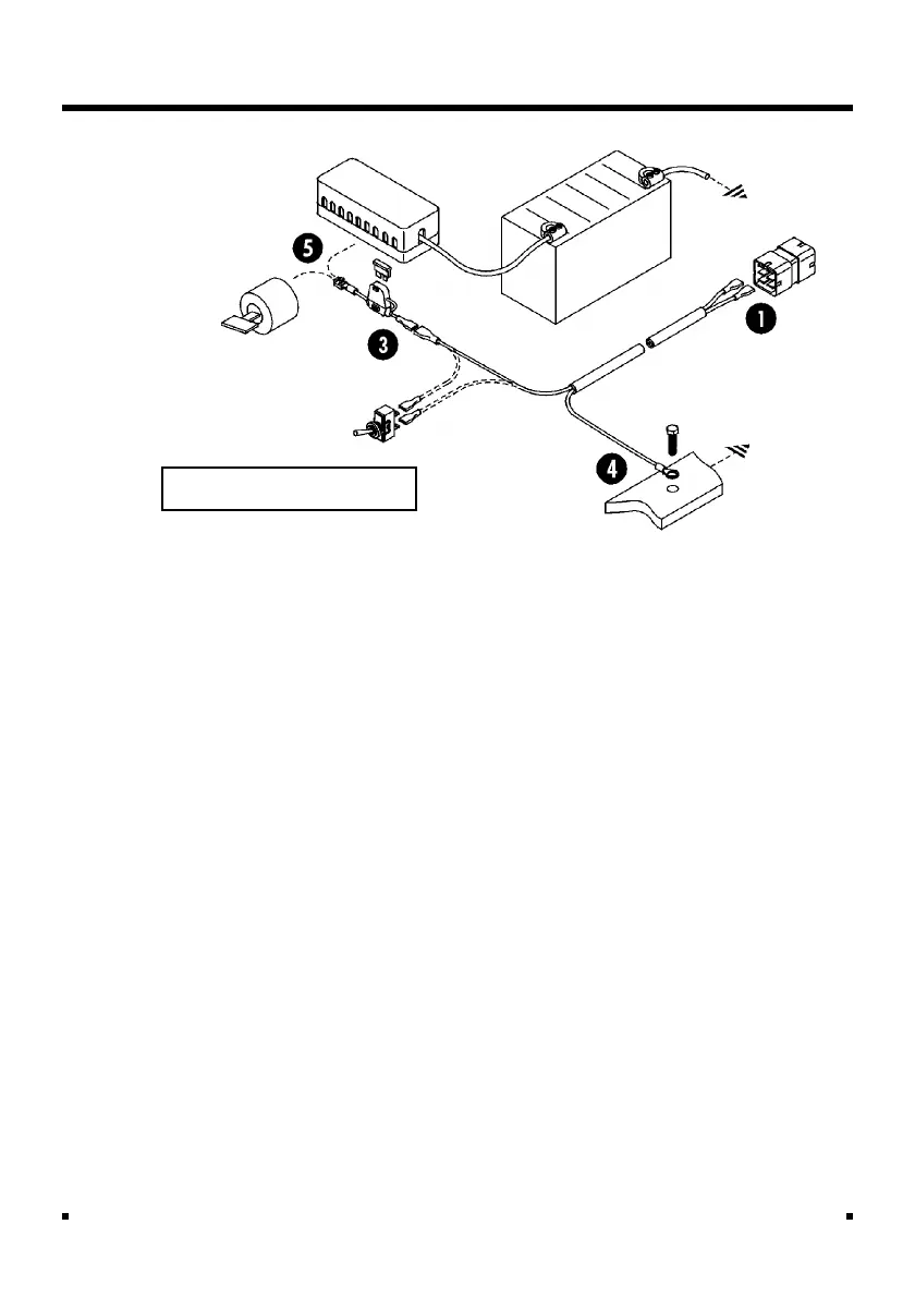
3. Connect the in-line fuse to the brown
wire of the power supply lead using the
male and female crimp provided.
4. Connect the 0V ring terminal to the
bodywork/chassis. Ensure connection
onto bare metal and that the connec-
tion point gives a good grounding path
to the battery.
5. Fit the piggyback crimp connector to
the other end of the fuse, and connect
to the supply point.
NOTE: If required, panel-mount the toggle
switch at a suitable point (1/2" dia drill
required) and connect between the +V
(brown) wire on the instrument end of
the supply lead and the blue Harting
terminal 4, using a suitable length of the
same gauge wire.
Installation
Fig. 25 12V Power Supply
Brown
Blue
Fusebox
Ignition
Switch