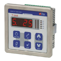
T-one ULS
Rev. 06/18 11/26
press up to move onto the next function.
11. F.34 appears on the display: use this function to set the minimum diameter value;
press enter and the function value set is displayed;
using the up or down keys set the minimum diameter value;
press enter to confirm and up to move onto the next function.
12. F.35 appears on the display:
position the reel with the minimum diameter on the unwinder/rewinder, position the diameter
sensor correctly and calibrate it, if necessary (if using the US3 sensor, see the relative user
manual);
press enter, the word “YES” flashes on the display for a few seconds if the gain calibration was
successful, otherwise the word “BAD” flashes (in this case see the note on page 19);
press up to move onto the next function.
13. F.36 appears on the display: use this function to set the tension set point control;
press enter and the function value set is displayed;
using the up or down keys set the value to 0 to control the set point by keypad or 1 to manage it
through the analog input (AIN0 or AIN1 depending on F.30);
press enter to confirm;
if the remote set point is enabled (F.36 = 1), press the up key to move onto the function 38 and
then onto the function 39 to set the analog reference;
if the remote set point is disabled (F.36 = 0), press the up key to move onto the function 39.
14. F.37 appears on the display;
adjust the analog input so that it supplies the minimum current or voltage to the instrument (e.g.:
4mA or 0V), depending if AIN0 or AIN1 is used (see F.30);
press enter, the word “YES” flashes on the display for a few seconds; then function 37 is
displayed again;
press up to move onto the next function.
15. F.38 appears on the display;
adjust the analog input so that it supplies the maximum current or voltage to the instrument (e.g.:
20mA or 10V), depending if AIN0 or AIN1 is used (see F.30);
press enter, the word “YES” flashes on the display for a few seconds; then function 38 is
displayed again;
press up to move onto the next function.
16. F.39 appears on the display: use this function to set the AUTO/STOP states control;
press enter and the function value set is displayed;
using the up or down keys set the value to 0 to control the states by keypad or 1 to manage them
through the digital input AUTO/STOP;
press enter to confirm and up to move onto the next function.
17. F.70 appears on the display: use this function to set the type of output to control the brake/clutch;
press enter and the function value set is displayed;
using the up or down keys set the value to 0 if you wish to use a 0÷10V output or 1 for a 4÷20mA
output;
press enter to confirm and up to exit the programming environment.

 Loading...