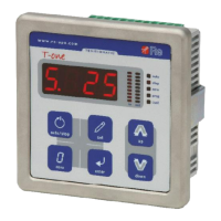
T-one ULS
Rev. 06/18 14/26
Instrument inputs / outputs description
Power supply
Pin 1 ( + ); Pin 2 ( - )
The instrument must be supplied with a continuous voltage of 24Vdc.
Digital inputs
AUTO/STOP
Pin 13
The input is active if F.39 = 1.
If it’s in the “HIGH” logic state (+24Vdc) the device switches to the AUTO state, otherwise it is in the STOP
state.
PRIORITY STOP
Pin 14
If it’s in the “HIGH” logic state (+24Vdc) the device switches to the PRIORITY STOP state, supplying the
constant output voltage set in function 8.
The PRIORITY STOP state has priority over all the other states.
Digital outputs
The digital outputs signal the alarms in normal work conditions (and if F.25 > 0 ), they operate the electro
valves if the Selematic management of the brake is active.
Alarm 0
Pin 15; Pin 16
Relay output that signals that the first alarm thresholds have been exceeded (F.26). A luminous/acoustic
signal or the digital input of any control device can be connected to the output (e.g. PLC).
Alarm 1
Pin 17; Pin18
Relay output that signals that the second alarm thresholds have been exceeded (F.27). A luminous/acoustic
signal or the digital input of any control device can be connected to the output (e.g. PLC).
EV.0
Pin 15; Pin 16
Relay output to connect to the electro valve to include or exclude SECT.2 of the brake.
EV.1
Pin 17; Pin18
Relay output to connect to the electro valve to include or exclude SECT.3 of the brake.
Analog input AIN0
Pin 20 ( + ); Pin 19 ( - )
The signal must be 4÷20mA, ΔI > 2,2mA.

 Loading...