Do you have a question about the Reach Technology RT-PoE4N and is the answer not in the manual?
Details the initial production version of the RT-PoE4N model and its identification string.
Explains the purpose of the Reach RT-PoE tester for functional production testing of PoE functionality.
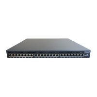
Describes the physical layout and components of the RT-PoE4N tester's front panel.
Lists the key features of the RT-PoE4N, including signature options, traffic handling, and cost-effectiveness.
Provides the physical dimensions of the RT-PoE4N unit, including depth, width, and height.
Details the power requirements and AC input specifications for the RT-PoE4N tester.
Specifies the operating temperature and humidity ranges for the RT-PoE4N unit.
States the warranty period and coverage provided by Reach Technology for the RT-PoE4N.
Confirms that no software license is required for the RT-PoE4N unit.
Explains that the unit performs self-calibration on power-on or when commanded.
Describes the power input location and the type of power supply used for the RT-PoE4N.
Details the rear serial console port, its RJ-45 connector, and RS-232 interface specifications.
Explains how to connect the PSE under test to the RT-PoE4N's 24 test ports for data and power testing.
Describes the 24 numbered RJ45 UUT ports and their data path connection logic.
Details the connectors on the rear of the unit, including the power DIN connector and serial console port.
Explains that no jumpers are needed and the unit accepts any polarity for power pairs.
Explains how the data path connects UUT ports to next ports for port-to-port testing.
Illustrates the power input for each power pair, showing voltage measurement and full wave bridge connections.
Details the IEEE 802.3at controller, signature options, class loads, and variable load capabilities.
Describes when the unit's fans engage and remain active based on port connections and temperature.
Explains the function of the green (power-good) and yellow (setting change) LEDs on each RJ45 connector.
Describes how to display available commands using the 'he' or '?' command.
Explains how to display the software and hardware version using the 'vers' command.
Details the 'err' command for reporting the unit's error flag status.
Explains how to change the unit's prompt using the 'host' command for identification.
Describes the 'baud' command to change the serial console baud rate, effective after cycle or boot.
Explains the 'echo' command for testing host-unit communication at higher baud rates.
Describes the 'boot' command to reset the system to its power-on state.
Explains how to use port or group prefixes to restrict commands to specific ports or groups.
Describes the 'cal' command for running internal calibration of class and power loads.
Details the 'cap' command to control the 10uF capacitor for capacitive signature or AC load.
Explains the 'cl' command to set the IEEE load class (0-4) for testing.
Describes the 'upoe' command for changing between regular, PoE+, and UPoE modes.
Details the 'conn' command to control relays connecting power load circuitry to UUT ports.
Explains the 'det' command to set the IEEE 802.3af/at detect signature (ok/hi).
Describes the 'ext' command for controlling the data path connection between adjacent ports.
Details the 'meas' command for measuring voltage on the main power pair.
Explains the 'meas2' command for measuring voltage on both main and alternate power pairs.
Describes the 'res' command to reset ports to a fully disconnected state.
Details the 'set' command to set power load values in milliamps.
Explains the 'st' command to return the 'Power Good' status and over-temperature conditions.
Describes the 'temp' command to report the temperature of the drain pin of the MOSFET load.
Describes the self-calibration process that occurs when the unit is powered on.
Lists common error messages, their descriptions, and the conditions that generate them.
Provides an overview of basic test setups for PSE and PD as defined by IEEE 802.3af.
Outlines RT-PoE commands and expected PSE actions for signature detection tests.
Details RT-PoE commands and expected PSE actions for class detection tests (0-4).
Lists RT-PoE commands and PSE actions for testing power status and overload conditions under 802.3af.
Describes testing power status and overload for 802.3at, referencing 802.3af procedures with modifications.
Details testing power status and overload for UPoE, referencing 802.3af procedures with modified 'set' commands.
Outlines RT-PoE commands and checks for data transmission testing under power for 802.3af.
Lists the measurement specifications for voltage and current, including accuracy and load guarantees.
| Product Type | PoE Injector |
|---|---|
| Data Rate | 10/100/1000 Mbps |
| Input Voltage | 100-240 VAC |
| PoE Standard | IEEE 802.3af/at |
| Ports | 4 |
| Operating Temperature | 0°C to 40°C |
| Power per Port | 30W |
| Humidity | 10% to 90%, non-condensing |