Reach PoE4N Tester Manual 1.4 08/09/2017 Page 8
4. Connectors and Jumpers
4.1. RJ-45 Ethernet Connectors
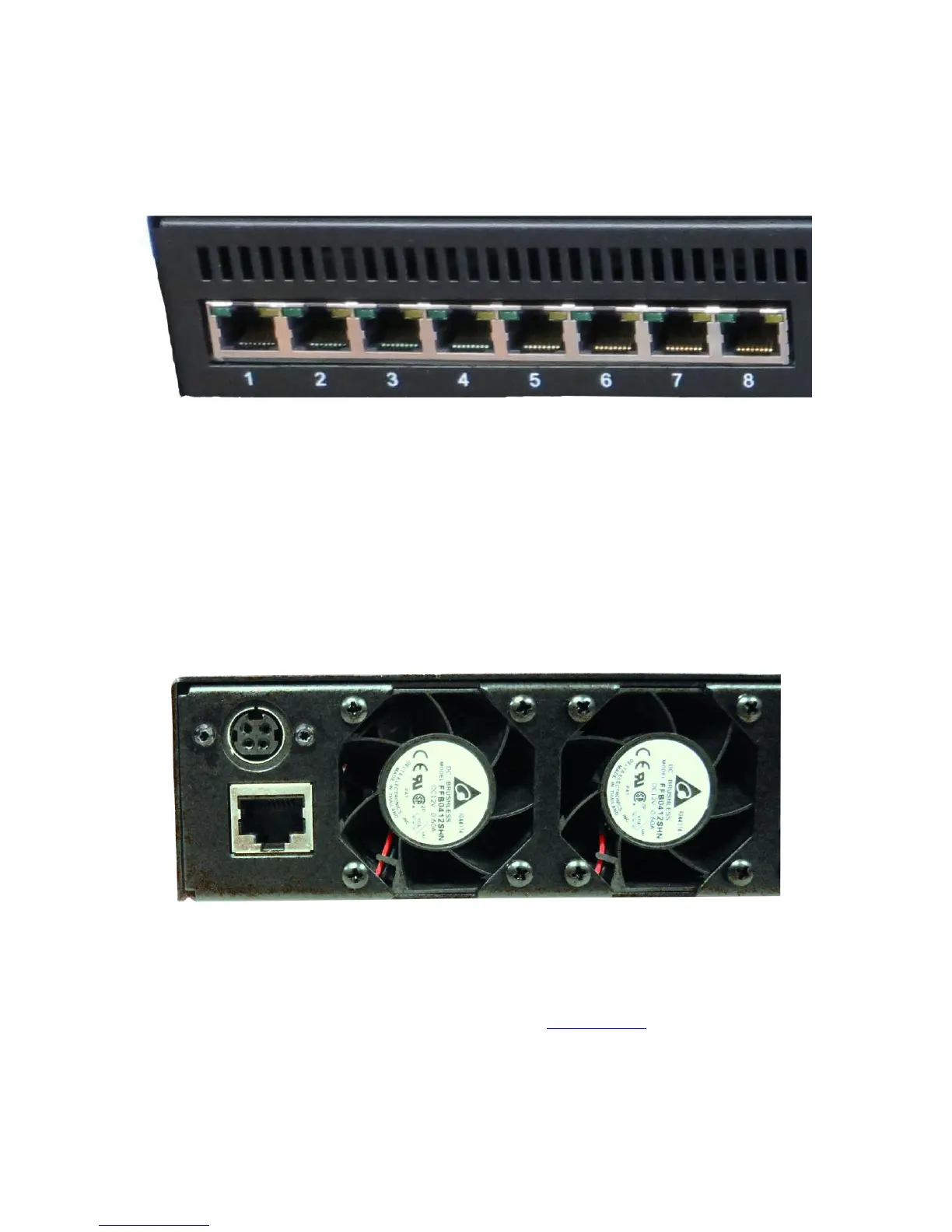
Picture 2: Far left side of RT-PoE4N front panel
There are 24 numbered UUT ports. The RJ connector should be cabled to the
corresponding PSE port using a standard Ethernet 1-1 jumper cable. When enabled via
software command, the data component of the port N (N=1,3,5,…) will be connected to
the data of port N+1 via Ethernet transformers and relays. This is a straight-through
connection, not a crossover.
4.2. Rear Connectors
Picture 3: Far left side of RT-PoE4N rear panel
The rear of the unit, left side is shown above. The power jack is a power DIN 4 pin with
lock type, KYCON KPPX-4. Pin 1,4 are 12VDC and pin 3,4 are GND. Below that is a
console connector RJ45 three wire RS232. See the Serial Console section for pinout.