2. Microcomputer peripheral circuits
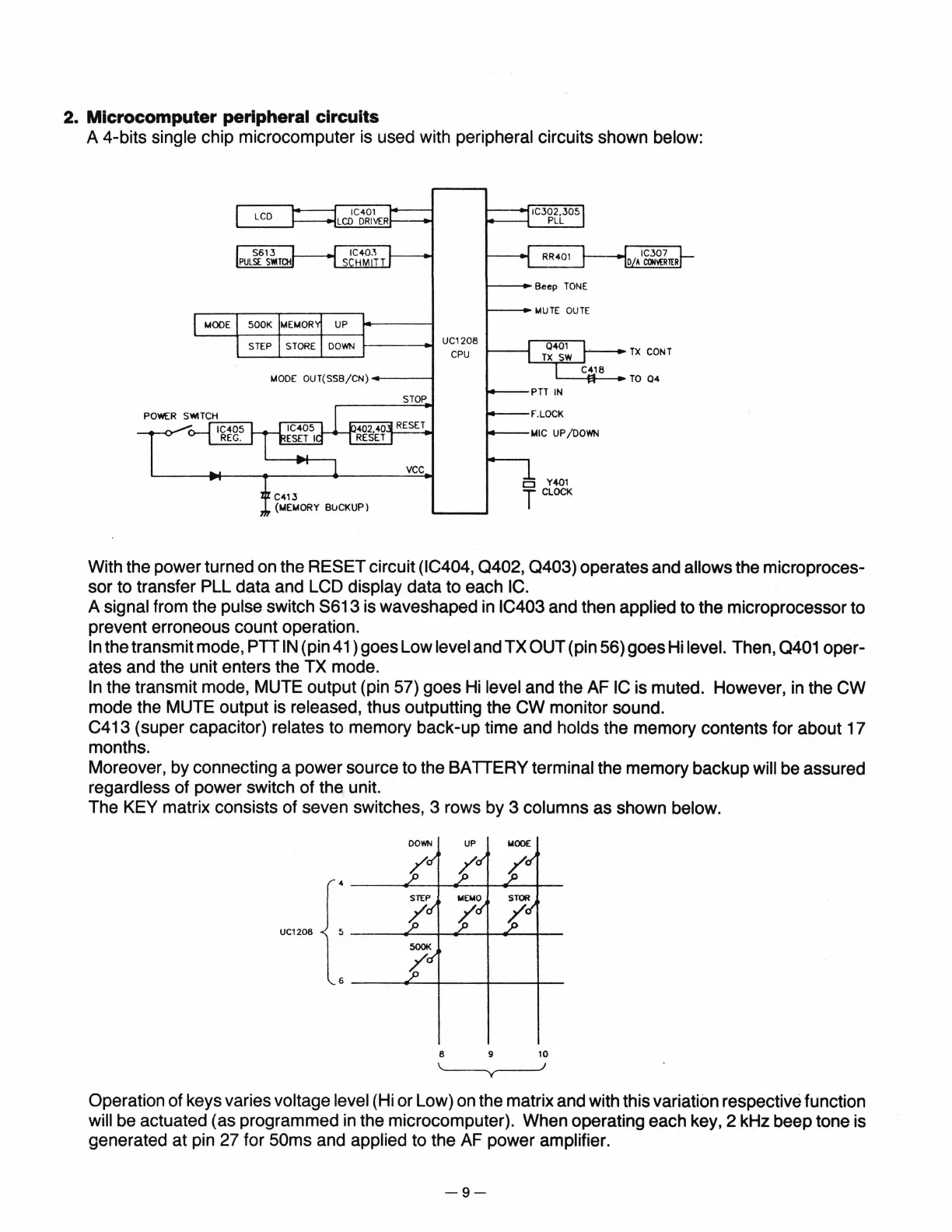
A 4-bits single chip microcomputer is used with peripheral circuits shown below:
~--~
UC1208
L----L--L....-..----1
CPU
loA
ODE
OUT(SSB/CN)
----t
STOP
RESET
vee
o Y401
T
CLOCK
With the power turned on the RESET circuit (IC404,
0402,
0403)
operates and allows the microproces-
sor to transfer PLL data and LCD
display data to each IC.
A signal from the pulse switch
8613
is waveshaped in IC403 and then applied to the microprocessor to
prevent erroneous count operation.
In
the transmit mode, PTT
IN
(pin 41) goes Low level and TX OUT (pin 56) goes Hi level. Then, 0401 oper-
ates and the unit enters the TX mode.
In
the transmit mode, MUTE output (pin 57) goes
Hi
level and the AF
IC
is muted. However,
in
the
CW
mode the MUTE output is released, thus outputting the
CW
monitor sound.
C413 (super capacitor)
relates to memory back-up time and holds the memory contents for about 17
months.
Moreover, by connecting a power source to the BATTERY
terminal the memory backup will be assured
regardless of power switch of the unit.
The KEY matrix consists of seven switches, 3 rows by 3
columns as shown below .
DOWN
UP
..
ODE
UC1208
6 9
10
Operation of keys varies voltage level (Hi or Low) on the matrix and with this variation respective function
will be actuated (as programmed
in
the microcomputer). When operating each key,
2kHz
beep tone is
generated at pin 27 for 50ms and
applied to the AF power amplifier.
-9-


 To Next Page