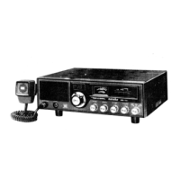
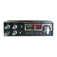
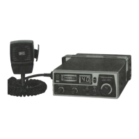
CIRCUIT DESCRIPTION
1. PLL circuit
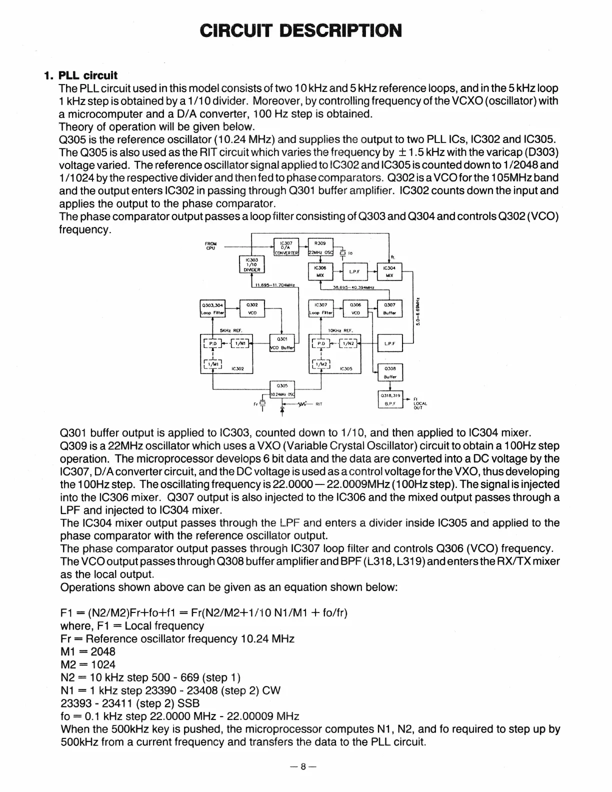
The PLL circuit used in this model consists of two
10kHz
and
5kHz
reference loops, and in the
5kHz
loop
1 kHz step is obtained by a 1
/1
0 divider. Moreover, by controlling frequency of the VCXO (oscillator) with
a microcomputer and a
D/
A converter, 1 00 Hz step is obtained.
Theory of operation
will be given below.
0305
is the reference oscillator
(1
0.24 MHz) and supplies the output to two PLL ICs, IC302 and IC305.
The
0305
is also used as the RIT circuit which varies the frequency by ± 1.5 kHz with the varicap (D303)
voltage varied. The reference oscillator signal applied to IC302 and IC305 is counted down to 1/2048 and
1
/1
024 by the respective divider and then fed to phase comparators.
0302
is a VCO for the 1 05MHz band
and the output enters
IC302
in
passing through 0301 buffer amplifier. IC302 counts down the input and
applies the output to the phase comparator.
The phase comparator output passes a
loop filter consisting of
0303
and
0304
and controls
0302
(VCO)
frequency.
fROM
CPU
r
!
"'
6
ori
0301 buffer output is applied to IC303, counted down to 1/1
0,
and then applied to IC304 mixer.
0309
is a 22M Hz oscillator which uses a VXO (Variable Crystal Oscillator) circuit to obtain a
1OOHz
step
operation. The microprocessor develops 6 bit data and the data are converted into a DC voltage by the
IC307,
D/
A converter circuit, and the DC voltage is used as a control voltage for the VXO, thus developing
the
1OOHz
step. The oscillating frequency is
22.0000-
22.0009MHz
(1OOHz
step). The signal is injected
into the
IC306 mixer.
0307
output is also injected to the IC306 and the mixed output passes through a
LPF and injected to IC304 mixer.
The
IC304 mixer output passes through the LPF and enters a divider inside IC305 and applied to the
phase comparator with the reference
oscillator output.
The phase comparator output passes through
IC307 loop filter and controls
0306
(VCO) frequency.
The
VCO output passes through
0308
buffer amplifier and BPF (L318, L319) and enters the
RX/TX
mixer
as the local output.
Operations shown above can be given as an equation shown below:
F1
=
(N2/M2)Fr+fo+f1
= Fr(N2/M2+1
/10
N1
/M1 + fo/fr)
where,
F1
= Local frequency
Fr
= Reference oscillator frequency 10.24 MHz
M1
= 2048
M2 = 1024
N2
=10kHz
step
500-
669 (step 1)
N1
= 1 kHz step
23390-
23408 (step 2) CW
23393-
23411 (step 2) SSB
to=
0.1 kHz step 22.0000
MHz-
22.00009 MHz
When the
500kHz key is pushed, the microprocessor computes N1, N2, and fo required to step up by
500kHz from a current frequency and transfers the data to the PLL circuit.
-8-