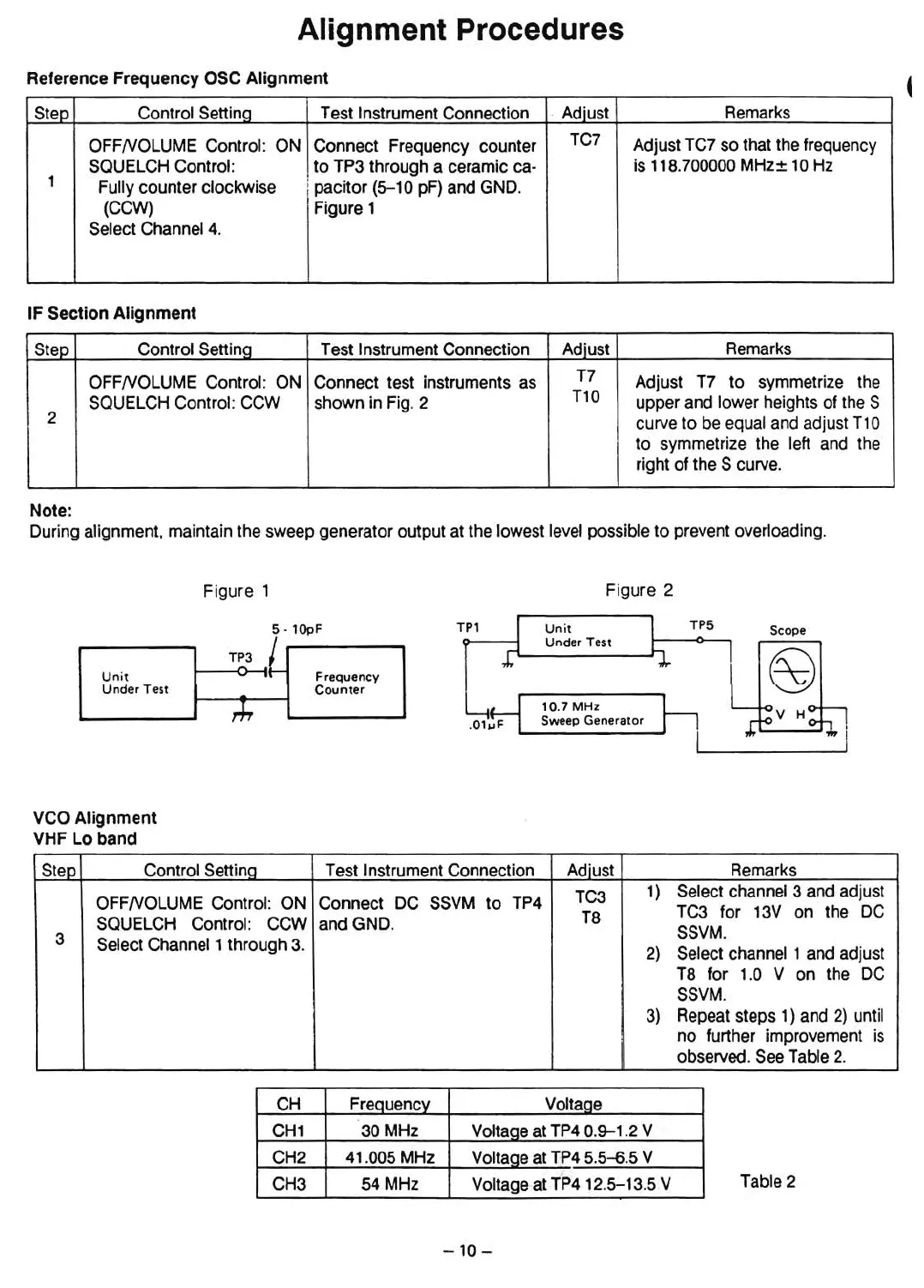
Alignment Procedures
Reference Frequency ose Alignment
Step
Contral Setting Test Instrument Connection
. Adiust
Remarks
OFFNOLUME Control: ON
Connect Frequency counter
TC7
Adjust TC7
50
that the frequency
SQUELCH Control. to TP3 through a ceramic ca-
is 11a.
700000
MHz± 10Hz
1
Fully counter clockwise
: pacitor (5-10 pF) and GND.
(CCW)
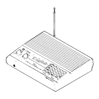
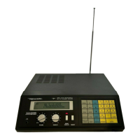
Figure 1
Select Channel 4.
IF Section Alignment
Step Control Setting Test Instrument Connection
Adiust
Remarks
OFFNOLUME Control: ON Connect test instruments as
T7
Adjust T7 to symmetrize the
SQUELCHControl: CCW
shown in Fig. 2
Tl0
upper and lower heights of the S
2
curve to be equal and adjust Tl 0
to symmetrize the left and the
right of the S curve.
Note:
During alignment. maintain the sweep generator output at the lowest level possible to prevent overloading.
Figure 1
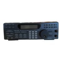
Figure
2
Scope
TPS
Unit
Under
Test
10.7 MHz
.01IJF Sweep
Generator
TPl
S·lOpF
I
TP3
-
Unit
-
"
Frequency
Under Test
Counter
rl-r
VCO Alignment
VHF Lo band
Step
Control Setting Test Instrument Connection Adiust
Remarks
OFFNOLUME Contral: ON Connect DC
SSVM
to TP4
TC3
1) Select channel 3 and adjust
SQUELCH
Contral: CCW and GND.
Ta
TC3 for 13V on the DC
3
Select Channel 1 through 3.
SSVM.
2)
Select channel 1 and adjust
Ta for 1.0 V on the DC
SSVM
.
3) Repeat steps 1) and 2) until
no further impravement is
observed. SeeTable 2.
CH
FreQuency Voltage
CH1
30 MHz
Vottaoe
at TP40.9-1.2 V
CH2
41.005 MHz
VoltaQe
at TP45.5-6.5 V
CH3 54 MHz Voltageat TP4 12.5-13.5 V
Table 2
-10
-
 Loading...