Step 3:
Step 4:
Step 5:
APPENDIX
VHF-MlD
Band Alignment for 20-9127
Circuit Revision
1. The following parts should be changed as shown below:
Ref. No.
! Lo Band
I
Mid Band Ref. No. Lo Band
I
Mld Band
I
C3
I
0.001,uF
!
33 pF
I
L2
4LNC-092
4LNC-122
C7
0.001 JlF
33 pF T1 7SSR-278
7SSR-287
C43
I
0.001,uF
I
15 pF
T2
7SSR-278
7SS0
-281
C44
33 pF
39pF
C301 Not Used
56pF
C45
33 pF 3 pF C302 Not Used
I
18 pF
C46
47 pF
39pF
0301
Not Used
BB609A
016
BB609A Not Used
2. Add
042
and
045
. and remove
044
.
VCO Alignment
Step 1: Connect a OC SSVM to TP 4 and ground.
Step 2: Program CH1, 2 and 3 as follows:
CH1 (68 MHz). CH2 (78 MHz), CH3 (88 MHz)
Select channel 3 and adjust TC3 for 12.0 V on the OC SSVM.
Select channel 1 and adjust T8 for 1.5 V on the OC SSVM.
Repeat steps 3 and 4 until no improvement Is observed.
The OC SSVM should show as below.
68 MHz Voltage of TP4 1.4-1 .6 V
78 MHz Voltage of TP4 6
.0-7
.0 V
88 MHz Voltage
ofTP4
11.5
-12
.5 V
RF Amp
A1
ignment
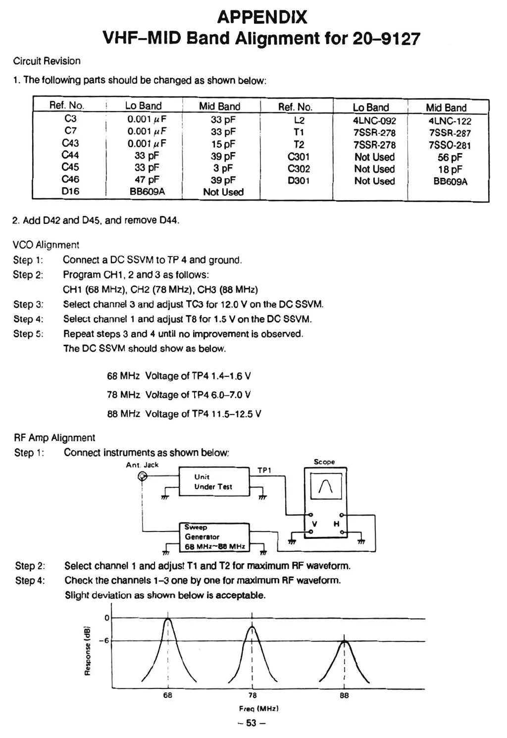
Step 1: Connect instruments as shown below:
Ant. Jack
Unit
Under Test
'---
--I
Sweep
Gener.tor
68
MHz-es
MHz
TPl
Scope
Step 2:
Step 4:
Select channel 1 aneladjust T1 and T2 for maximum RF waveform.
Check the channels
1-3
one by one for maximum RF waveform.
Slight deviation as shown below is acceptable.
0
iii
~
- 6
~
c
0
!t
Ol
a::
68
78
Freq IMHz )
- 5
3-