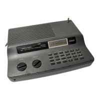
PREPARATION
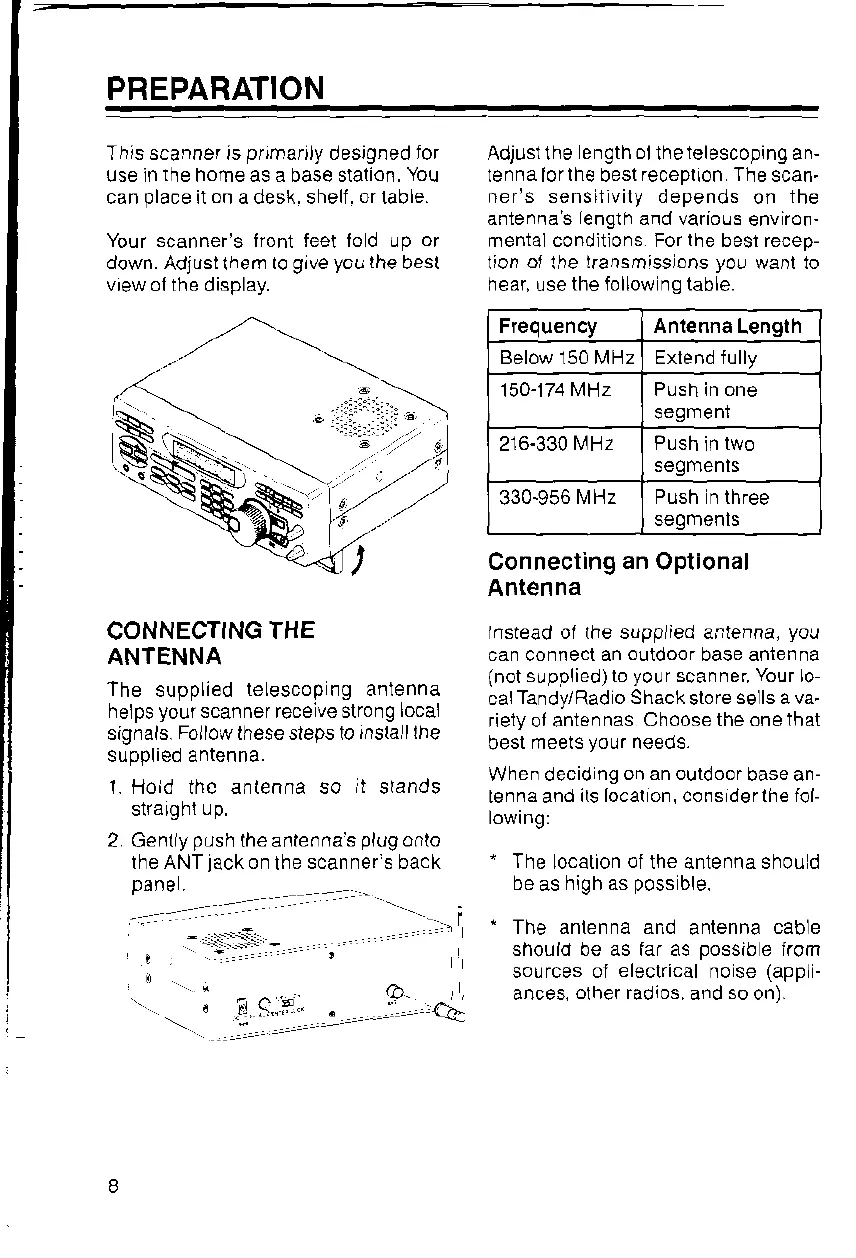
This scanner is
plrnarjly
designed
ior
use ln
the
horne as a base station,
You
can
place
it
on
a desk. shell.
or
table.
Yout scanner's iront feet lod up
or
down.
Adjust them
to
give
you
lhe
best
vrew ol the display.
Adjust the
ength ol
the
telescoping
an-
tenna lor
lhe
best
recepllon Thescan.
ner's sensillvily depends
on
the
antenna s
length
and various
environ-
rnental conditions For
lhe
be$ recep-
lion
ol
the
lransmissrons
yo!
wanl to
hear, use
the follow ng table.
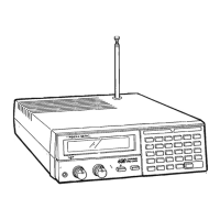
CONNECTING
THE
ANTENNA
The
supplied
teLescop rg antenna
heJps
your
scanner recelve strong
local
signals.
Follow
these steps to
rnslalllhe
supplied antenna.
1. Hoid thc antenna so
it
stands
strarght
up.
2 Gentlypush theanlennasplogonlo
the ANT
lack
on
the
scanner's back
pane
I
-
.1
-::.
-
.
.
!9,..
::
Q
=..-
Connecting
an
Optional
Antenna
lnstead ol the supplied antenna,
you
can connect an
outdoor
base antenna
(not suppli-"d) to
your
scanner
Your
lo-
calTandy/Radio
Shack
store
sells ava.
riety ol antennas
Choose the one
lhat
best
meets
your
neeoa.
When decid
ng on an outdoor
base an-
tenna and
its local on, cons derthe fol-
lowrng:
"
The
location
ol
the antenna shou d
ha !< hi^h r<
^^<(
hlo
'
The anlenna and
antenna
cable
should be as far as
possible
irom
sources oi
electrical
n0se
(appl-
ances,
olher radios,
and
so
on).
Frequency Antenna
Length
Below 150 MHz Erlend fully
150-174
MHz Push in one
segmenr
216-330lVHz
segmenls
330-956
MHz Push n three
segmenls
 Loading...