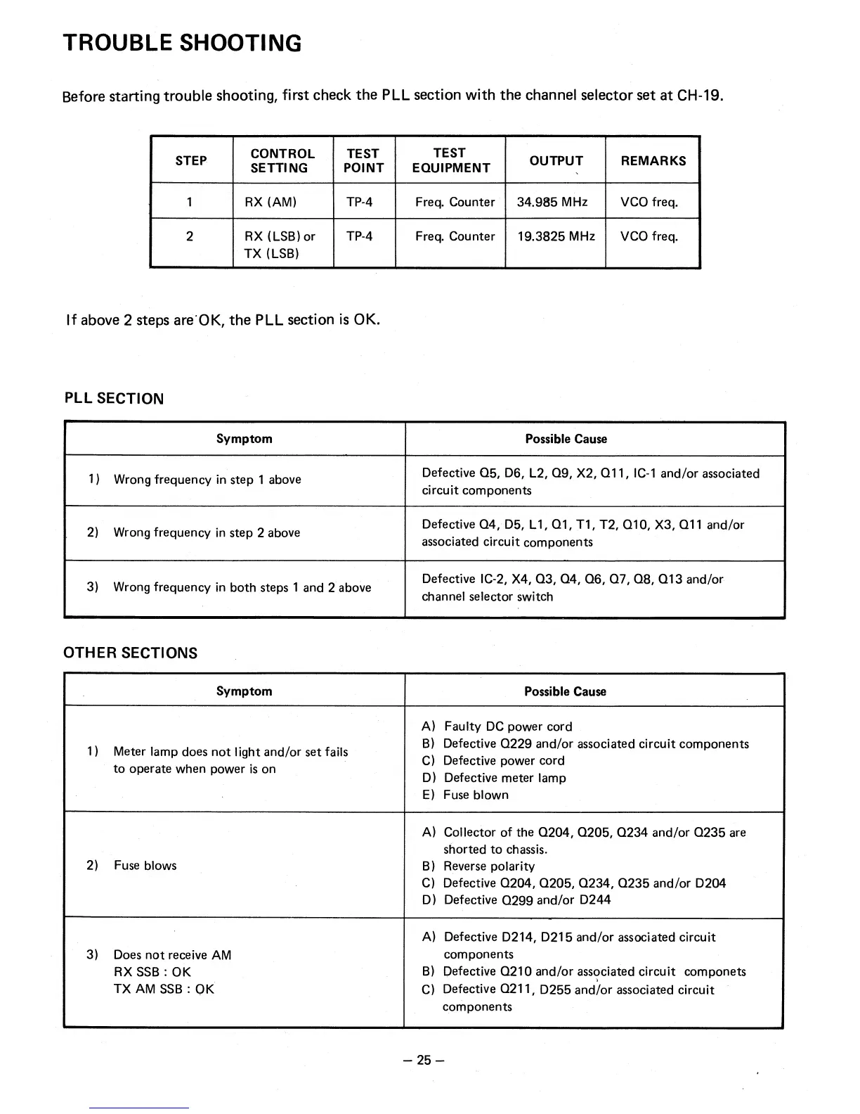
TROUBLE SHOOTING
Before starting trouble shooting, first check the PLL section with the channel selector set at CH-19.
STEP
CONTROL
SETTING
TEST
POINT
TEST
EQUIPMENT
OUTPUT
REMARKS
1
RX (AM)
TP-4
Freq. Counter
34.985 MHz
VCO freq.
2
RX (LSB) or
TX (LSB)
TP-4
Freq. Counter
19.3825 MHz
VCO freq.
If above 2 steps are
.
OK, the PLL section is OK.
PLL SECTION
Symptom
Possible Cause
1)
Wrong frequency in step 1 above
Defective Q5, D6, L2, Q9, X2, Q11, IC-1 and/or associated
circuit components
2)
Wrong frequency in step 2 above
Defective Q4, D5, L1, Q1, Ti, T2, Q10, X3, Q11 and/or
associated circuit components
3)
Wrong frequency in both steps 1 and 2 above
Defective IC-2, X4, Q3, Q4, Q6, Q7, Q8, Q13 and/or
channel selector switch
OTHER SECTIONS
Symptom
Possible Cause
1)
Meter lamp does not light and/or set fails
to operate when power is on
A)
Faulty DC power cord
B)
Defective Q229 and/or associated circuit components
C)
Defective power cord
D)
Defective meter lamp
E) Fuse blown
2)
Fuse blows
A)
Collector of the Q204, Q205, Q234 and/or Q235 are
shorted to chassis.
B)
Reverse polarity
C)
Defective Q204, Q205, Q234, Q235 and/or D204
D)
Defective Q299 and/or D244
3)
Does not receive AM
RX SSB : OK
TX AM SSB : OK
A)
Defective D214, D215 and/or associated circuit
components
B)
Defective Q210 and/or associated circuit componets
C)
Defective Q211, D255 and/or associated circuit
components
— 25 —