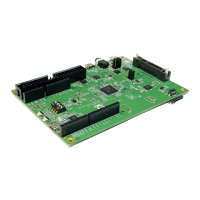
The RTL8762E Evaluation Board (EVB) is a hardware platform designed to assist customers in developing their own Bluetooth® applications. This user manual, version V1.0 dated 2021/07/02, provides comprehensive instructions for using the board.
Function Description:
The RTL8762E EVB serves as a development environment for Bluetooth® applications based on the 8762E chip. It integrates various components to facilitate testing, debugging, and power management for custom designs. Key functionalities include:
- Voltage Conversion: The board incorporates a voltage converter to provide different power levels required by the system.
- Motion Sensing: A 6-axis motion sensor is included, enabling the development of applications that require orientation, acceleration, or gyroscope data.
- User Interface Elements: The EVB features 4 LEDs and 6 keys for basic input and output, allowing developers to implement simple user interfaces or status indicators.
- Battery Support: It includes holders for both button batteries (CR2032) and Li-ion batteries, offering flexibility in power sources for portable applications.
- UART Communication: An onboard USB to UART converter (FT232RL) is provided for serial communication with a PC, primarily for acquiring log data and debugging.
- Debugging Interface: The board supports SWD (Serial Wire Debug) for in-depth debugging of the RTL8762E chip.
Important Technical Specifications:
The RTL8762E EVB offers several power supply options and interfaces:
- Power Supply Selection (Mark 10):
- 3V3: Powered by the USB source on the evaluation board, providing 3.3V to the IC.
- VCR2302: Powered by a CR2302 battery (located on the rear of the board).
- 2V5: Powered by the USB source, providing 2.5V to the IC, typically used for eFUSE burning.
- Li-ion Battery: The evaluation board can also be powered by a Li-ion battery via the Li-ion battery holder (Mark 15). Note: If using a Li-ion battery, the jumper on Mark 10 must not be connected.
- Voltage Regulators (Mark 13/14): AMS1117 3.3V and AMS1117 2.5V LDP chips convert 5V to 3.3V and 2.5V respectively when powered by a Li-ion battery.
- Micro USB (Mark 12): Provides 5V power supply and acts as a UART communication port when connected to a PC.
- IO Ports:
- Mark 1: 2 x 15 IO Jumper.
- Mark 19: 2 x 14 IO Jumper.
- UART/LOG Test Jumper (Mark 3): Configurable for HCI UART Test or Log Test.
- G-sensor Interface (Mark 7): I2C interface for the 6-axis motion sensor. Jumper connections J18 and J19 are shorted for I2C, connecting the I2C signal line to M3_2 and M3-3. The INT line can be connected to M2_2 via J20.
- SPI Interface (G-sensor): If SPI is used, R1 must be removed. AD0 and nCS test points connect to specified IO ports with jump wires, and J18 and J19 are shorted.
- LEDs (Mark 16): 4 independent LEDs for customized applications. Corresponding jumpers (J24 to J27) must be connected.
- Keys (Mark 18): RESET key and 5 independent keys. Debouncing capacitors are not mounted by default but can be added.
- FT232 Chip (Mark 11): The USB to UART converter chip.
- SWD Interface (Mark 20): Used for SWD debugging.
Usage Features:
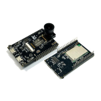
- Easy Module Connection: The daughter board, containing the main RTL8762E module, connects to the motherboard via a connection socket (Mark 5). Proper orientation is crucial, aligning the PCB antenna mark on the daughter board with the silkscreen mark on the motherboard.
- Flexible Powering Options: Developers can choose between USB power (3.3V or 2.5V), a CR2032 button battery, or a Li-ion battery, depending on their application requirements.
- Log Acquisition: The onboard USB to UART converter allows for easy acquisition of log data from the P0_3 pin to a PC, facilitating debugging and monitoring. Jumpers J15 and J17.1 must be connected for this functionality.
- Motion Sensor Integration: The 6-axis motion sensor (Mark 6) is powered by VDD_DEV, requiring J6 to be connected. It supports both I2C and SPI interfaces, offering flexibility in sensor data acquisition.
- Customizable LEDs and Keys: The 4 independent LEDs and 6 keys provide basic I/O for developing and testing application logic. LEDs can be connected to specified IO ports using jump wires for custom control.
- Current Measurement Points: Dedicated test points (VDD_DEV, VDD_BAT, VDD_IO) are reserved for current testing, allowing developers to measure the power consumption of different parts of the EVB. J23 must be disconnected during power consumption tests.
Maintenance Features:
- Revision History: The manual includes a revision history, with the initial version V1.0 released on 2021/07/02, indicating ongoing documentation updates.
- Troubleshooting Notes: The manual provides important notes for specific operations:
- When powering with a Li-ion battery, ensure the jumper on Mark 10 is removed.
- For current measurement, it is crucial to disable LOG printing in the SDK and disconnect UART and SWD debuggers to avoid affecting measurement accuracy.
- If current measurement at 3V is needed, the onboard power supply should be replaced with an external 3V DC power supply.
- When measuring current at 3.0V, external DC power should be used instead of the onboard supply.
- For the 6-axis motion sensor, ensure J6 is connected to power VDD_DEV.
- Debouncing capacitors for keys (Mark 18) are not mounted by default but can be soldered on if needed to reduce ripples during button presses.
- LED jumpers (Mark 17) should be removed when testing power consumption, as lighted LEDs can affect the test results.