RTL8762E Evaluation Board User Manual
11
Copyright 2021 Realtek Semiconductor Corporation.
All Rights Reserved.
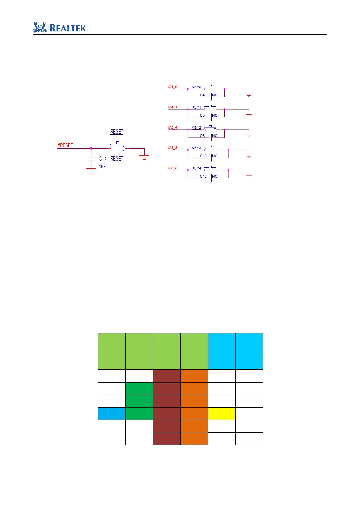
3) Mark 18: RESET key and 5 independent keys, as shown in Figure 1-9.
Note: Debouncing capacitors and internal pull-up resistor make up a filter circuit to reduce ripples when
buttons are pressed. However, it can also affect the result of keyboard array scan. Capacitors are not mounted
on board by default. User can solder 0.1uF capacitor on pads when necessary.
Figure 1-9 Schematic of Keys
4) Mark 11: FT232 chip.
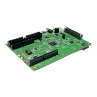
1.3 Pin Allocation on Motherboard of Evaluation Board
When edges of daughter board are flush with the white lines and PCB antenna on daughter board is aligned with
silkscreen mark on motherboard, the pins on daughter board are properly inserted; otherwise it is necessary to be
cautious about improper connection.
Pin allocation of motherboard is listed as follows:
Table 1.1 IO Pin Allocation on Motherboard & Daughterboard