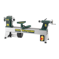
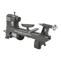
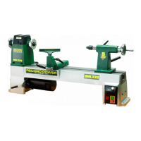
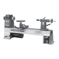
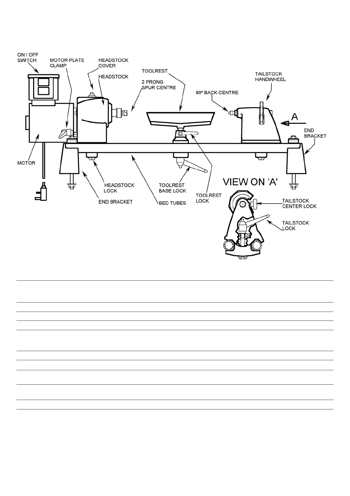
5. Control Identification & Function
CONTROL FUNCTION OPERATION / COMMENT
ON / OFF Switch Starts and Stops Motor. No Volt Release switch Green (1) START, Red (0) STOP. If
power supply is interrupted during operation lathe will not
restart until START button is pressed.
Tool rest Supports turning tool Position as per lathe safety instructions (section 2, part 5)
2 Prong drive Holds and drives workpiece for spindle turning Provides driving force from motor. Firm contact required.
90º Back centre Supports free end for spindle turning Provides support for end of spindle which is not driven.
Headstock lock Locks headstock to bed tubes. Lock from inside headstock using a 19mm (3/4”) wrench. Turn
clockwise to lock . Locate and lock firmly before mounting
workpiece.
Toolrest lock Locks toolrest post into base Turn clockwise to lock.
Toolrest base lock Locks toolrest base to bed tubes Turn clockwise to lock
Tailstock lock Locks tailstock to bed tubes Turn right to lock. Position tailstock along bed tubes before
locking
Motor plate clamp Locks motor when belt is tight. Loosen to adjust belt for selected speeds. Tighten when belt is
properly positioned.
Tailstock handwheel Moves 90º back centre into workpiece Rotate clockwise to move 90º back centre towards workpiece.
Tailstock centre lock Locks 90º back centre Turn clockwise to lock after positioning 90º back centre with
handwheel.