Do you have a question about the Record Power CL4-CAM and is the answer not in the manual?
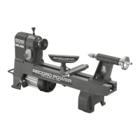
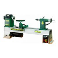
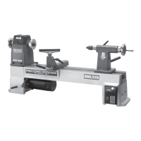
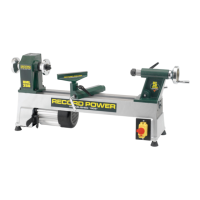
Introduces the Record Power CL3-CAM and CL4-CAM professional lathes.
Highlights critical safety symbols to be aware of before operation.
Details symbols requiring specific actions before or during operation.
Explains symbols indicating potential risks and hazards during operation.
Covers PPE, appropriate dress, and general safe operating procedures.
Discusses maintaining a clear workspace, lighting, and avoiding hazardous environments.
Details safe storage, electrical connections, and avoiding unintentional starts.
Covers working within capacities, cable care, securing workpieces, and staying alert.
Addresses specific risks and precautions for woodturning operations.
Provides guidance on maintaining the lathe and keeping tools sharp.
Outlines the 5-year guarantee, its coverage, and exclusions.
Details how to make a claim and limitations of liability.
Lists key dimensions, power, speeds, and noise levels for the lathes.
Details the speed variations achievable with different pulley configurations.
Explains the kinematic design philosophy for stability and performance.
Lists all parts included in the shipping container for assembly.
Provides a visual guide to the components for assembly.
Specifies requirements for a sturdy bench or stand for lathe installation.
Guides on positioning end brackets and ensuring kinematic alignment.
Details the process of attaching angle straps and bed bars for structural integrity.
Illustrates the 3-point contact kinematic principle for stability.
Step-by-step guide for fitting the tailstock assembly to the lathe bed.
Explains how to adjust the tailstock cam sensitivity.
Instructions for assembling the banjo and tool rest components.
Guidance on adjusting the tool rest cam sensitivity.
Initial steps for disassembling and preparing the CL3-CAM headstock.
Continues CL3-CAM headstock assembly, including saddle and handle fitting.
Completes CL3-CAM headstock assembly and pulley re-fitting.
Steps for removing the headstock cover and belt tensioner for CL4-CAM.
Instructions for attaching the motor plate and pivot pin to the VSLK unit.
Guides on fitting the motor pulley, belt, and completing CL4-CAM assembly.
Procedures to ensure correct pulley alignment and minimize vibration.
Steps for accurately levelling the lathe using spirit levels and centre alignment.
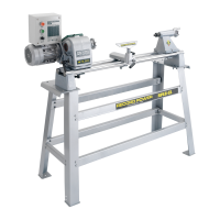
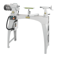
Visual confirmation of the assembled CL3-CAM and CL4-CAM lathes.
Details how and when to apply oil to the bronze bearing for optimal performance.
Instructions for the initial run-in period to ensure bearing longevity.
Defines the lathe's purpose and general safety for woodturning.
Guides on securely mounting wood blanks using faceplates or centres.
Explains the critical importance and method of positioning the tool rest.
Describes the use of gouges and skew chisels for shaping wood.
Provides recommendations on appropriate speeds for different turning operations.
Identifies the VSLK unit controls and their functions for the CL4-CAM.
Identifies the switch box controls and their functions for the CL3-CAM.
Steps for safely restarting the lathe after a power failure or overload.
Guidance on selecting speeds and safe practices during operation.
Details necessary adjustments like tailstock and toolrest before starting.
Speed chart for CL3-CAM based on pulley positions.
Detailed speed chart for CL4-CAM with speed settings and pulley steps.
Explains the specific controls of the CL4-CAM Variable Speed Unit (VSLK).
How to start, adjust speed, and stop the CL4-CAM lathe.
How to operate the CL3-CAM using its dedicated switch box.
Step-by-step guide for adjusting the belt to different pulley positions.
Instructions for changing the drive centre or other headstock attachments.
Detailed procedure for adjusting the bronze taper bearing for smooth operation.
Guidance on lubricating the bearing to prevent dry running and wear.
Detailed steps for replacing the drive belt or the bronze bearing assembly.
How to remove the spindle and bearing from the headstock casting.
Steps for refitting the spindle and bearing assembly into the headstock.
Final steps for belt tensioning and bearing adjustment after replacement.
Diagnoses and remedies for motor problems like not starting or cutting out.
Troubleshooting common issues like excessive noise, vibration, and incorrect alignment.
Illustrated diagram showing main lathe components with part numbers.
Illustrated diagram of the VSLK unit with part numbers.
Comprehensive list of part numbers, descriptions, and quantities.
Explains wire colour coding and connection for 230V single-phase supply.
Explains wire colour coding and connection for 400V three-phase supply.
Schematic diagram for the CL3-CAM electrical connections.
Schematic diagram for the CL4-CAM electrical connections.
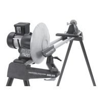
Lists all parts included in the CL3/B bowl turning attachment package.
Instructions for attaching the CL3/B bracket to the lathe headstock end.
Guidance on adjusting the CL3/B for optimal workpiece turning.
How to secure the CL3/B for standard turning tasks.
How to adjust the headstock for maximum clearance with the CL3/B.
Detailed diagrams and parts list for the CL3/B attachment.
Lists all parts included in the RPLB24-48 lathe stand package.
Technical details and dimensions of the RPLB24-48 lathe bench.
Initial steps for identifying and preparing bench components for assembly.
Steps for assembling the leg sub-assemblies and end rails of the bench.
How to attach the top plates and complete the bench assembly.
Instructions for firmly fixing the CL3-CAM/CL4-CAM lathe to the assembled bench.
Guidance for mounting other lathe models, like the DML36SH-CAM.
Declares conformity with relevant EU directives for machinery and safety.
| Type | Wood Lathe |
|---|---|
| Swing Over Bed | 305 mm |
| Taper | MT2 |
| Speed Range | 500 - 2000 RPM |
| Spindle Thread | 1 inch x 8 TPI |