29
10. Lathe Operation - cont.
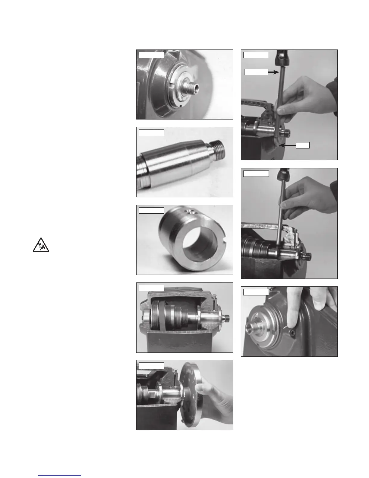
Fig.10.9 Fig.10.14
Fig.10.15
Fig.10.10
Fig.10.11
Fig.10.12
Fig.10.13
Fig.10.16
ADJUSTING THE BRONZE TAPER
BEARING
The Tapered Bronze Bearing System fitted to
CL3-CAM and CL4-CAM is one of the finest
bearing systems available and a long established
and well proven engineering solution. Take time
to learn the correct maintenance and adjustment
of this system and you will enjoy smooth running
accuracy with high load bearing capacity for
many years.
The bearing is visible as a brass coloured sleeve
with tightening rings either side, Fig 10.9. It is
made from phosphor bronze, specially formulated
to resist wear providing that it is oiled correctly.
If you dismantle the headstock you will find that
the main shaft has a taper machined on the end,
Fig 10.10, and the bronze bearing is tapered
internally to match, Fig 10.11.
Fig 10.12 shows in cross section how these fit
together, with the two tapers seating together,
the bearing being held in place with the two
locking rings. Adjustment is made by moving the
bronze bearing along the spindle, i.e. tightening
the two tapers up on each other.
If you suspect the bearing does need adjusting,
screw on a faceplate to give extra leverage, and
then feel for movement, Fig 10.13. If you detect
the slightest amount of play the bearing has to
be tightened.
Adjustments should be made when the lathe is
up to operating temperature, if it hasn’t been
run this will take about 5 minutes running then
disconnect the lathe from the power source and
begin adjustment process.
The spindle is fixed and the two tapers can only
be brought closer together by moving the bronze
bearing along the spindle. Slacken the ring at the
front of the headstock, Fig 10.14, by knocking it
gently round anti clockwise using the Brass Rod
provided, Fig 10.15.
Now tighten the inner ring by turning it the same
way, Fig 10.16, to pull the sleeve along and
tighten up to the spindle taper. The adjustment
required is very small so do not move the rings
more than a fraction of a turn at a time. Keep
doing this until the play is removed. If you overdo
it the bearing will lock up tight – if this happens
release the inner ring very slightly and tighten the
outer ring.
Please note: The grub screw on the back
of the headstock is to prevent the bearing
turning, Fig 10.16, and has nothing to
do with the function of the bearing
adjustment. DO NOT adjust this screw.
BEARING LUBRICATION
Do not the allow the bearing to dry out between
lubrications. Over-lubrication may result in oil
being thrown out and on to the workpiece or
lathe. Lubricate before each use. For optimum
performance we recommend the use of Record
Power spindle oil – RPSO-100. If not available use
automotive grade 30W oil. For further information
on this procedure see section 7 of the manual.
Ring
Brass rod



 To Next Page