16
6. Assembly Instructions - cont.
CL3-CAM Headstock Assembly
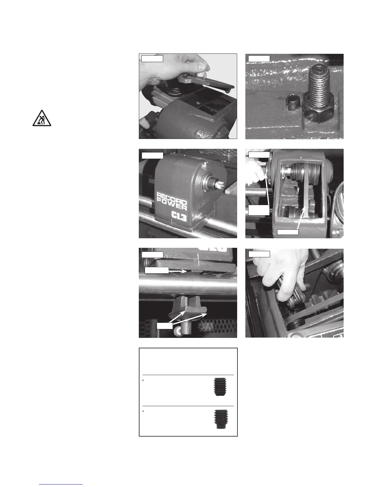
16. Remove the cover plate from the headstock
using the Allen key, Fig.6.23.
17. Place the saddle on to the bed bars to the
left hand side of the toolrest with the single pad
and the label to the front of the lathe Fig. 6.24.
Caution: This component is very heavy
and assistance should be sought.
18. Insert the headstock locking handle (item
12) through the remaining square strap and
offer this up through the saddle and into the
headstock, ensuring the side with 2 pads is at
the front, opposing the single pad of the head
stock, Fig. 6.25.
19. Ensuring that the hex head nut is located
against the wall of the recess inside the
headstock, tighten the locking bar into the nut
securing the headstock assembly Fig. 6.26.
20. The motor, pulley and belt now need to
be re-fitted. Please follow steps 2- 6 on the
previous page in reverse order to re-fit.
Rotate the thread protector (item 23) by
hand and inspect the drive belt on the pulleys
ensuring that it runs true Fig.6.27. If it doesn’t,
slide the stepped pulley along the motor shaft
until the correct position is achieved and the
belt is aligned straight.
21. Now tighten the dog grub screw which has
been inserted previously. Then take the second
grub screw and tighten this in on top of the dog
grub screw locking the position of the motor
pulley Fig.6.28.
Finally replace the headstock cover plate and
secure this with the Allen bolt.
The assembly of the CL3-CAM lathe is now
complete, Fig. 6.46.
Fig.6.24
Fig.6.27
Drive belt
Thread
Protector
TIP
The pulleys lock onto the shafts using two
grub screws.
A knurled base grub screw
which locates into the
dog grub screw.
Then the dog grub screw
locates into the groove
on the shaft.
Fig.6.28
Fig.6.25
Single pad
2 pads
Fig.6.23 Fig.6.26
 Loading...