13
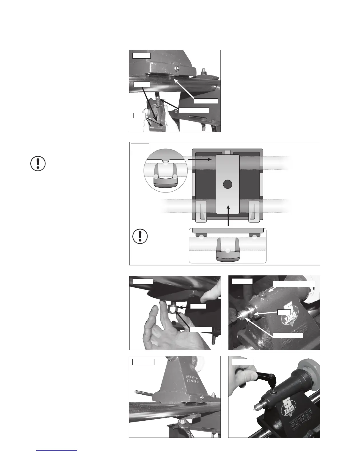
Attaching the tailstock
1. Place the tailstock onto the bed bars at
the right hand end of the assembly, again
noting that the single point raised area for the
kinematic design is at the front of the lathe,
Figs.6.8a & 6.8b.
2. Introduce the square strap underneath the
bed bars, ensuring that the double point recess
is to the front of the lathe opposing the raised
area on the tailstock, Figs.6.8a & 6.8b.
3. Place the washer onto the tailstock screw and
tighten the nyloc nut to secure the assembly
Fig.6.9.
4. Use a spanner (not supplied) to tighten the
Nyloc nut on the underside of the tailstock
assembly Fig.6.10.
Please note: Sensitivity of the cam is
adjusted with this nut. To reduce travel
on the cam and increase clamping force,
tighten the nut. To increase travel on
the cam and reduce the clamping force,
slacken the nut.
5. Now take the tailstock centre and place into
the barrel of the tailstock. On the top of the
tailstock there is a small hole - this is where the
pre-installed brass pad is found Fig. 6.11.
6. Screw in the tailstock ratchet handle (item
13), Fig. 6.12. The tailstock assembly is
now complete.
6. Assembly Instructions - cont.
Fig.6.11
Tailstock centre
Brass pad pre-installed
Barrel
Fig.6.12
Fig.6.9
Washer
Nyloc Nut
Fig.6.10
Fig.6.8a
Raised area
Tailstock screw
Recess
2 pads
Fig.6.8b
Tailstock from
below
Tailstock
from rear
Tailstock
from front
Kinematic principle
in use - 3 points of
contact created
 Loading...