17
Changing the Spindle Speed
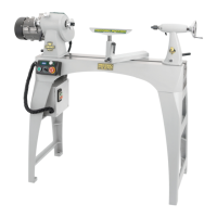
The DML320 features a 3 step pulley system. The drive belt should be
positioned on the corresponding pulleys as shown in Fig 10.14 to achieve
the speed range required.
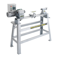
To access the spindle pulley, remove the hex head socket screw from the
front of the headstock cover using a 4 mm hex wrench, Fig 10.15.
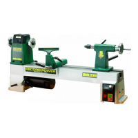
To access the motor pulley, remove the hex head socket screw from the
motor pulley access hatch and open the door, Fig 10.16.
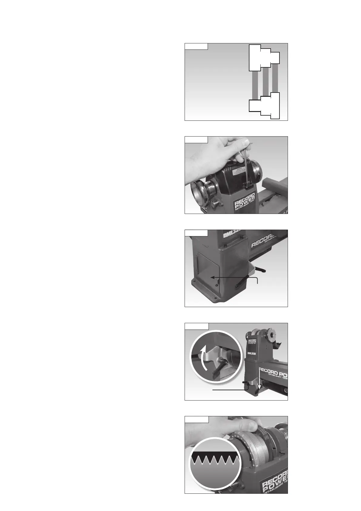
Loosen the motor securing lever and raise the motor to its highest position
using the motor positioning lever, Fig 10.17, and re-tighten the motor
securing lever to hold it in place. The drive belt will now be loose enough to
place in the desired position, Figs 10.18 and 10.19.
Ensure the V grooves of the drive belt are positioned in the grooves of the
pulleys as shown in Fig 10.18. Turn the hand wheel by hand to check they
are located correctly.
Once the drive belt is positioned as desired, loosen the motor securing
lever and lower the motor until it is at its lowest position - The weight of
the motor provides sufficient tension to the drive belt. Tighten the motor
securing lever, close the headstock cover and close the motor pulley access
hatch cover.
10. Operation
Fig 10.15
Fig 10.18
Fig 10.14
Position RPM
1 250 - 750
2 550 - 1650
3 1300 - 3850
2
3
1
SPINDLE
PULLEY
MOTOR
PULLEY
Fig 10.16
Motor pulley
access hatch
Fig 10.17
Motor
securing
lever
Motor
positioning lever
Pulley
Belt