14
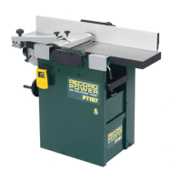
Once the whole fence assembly is installed, check that the fence is square
to the table. If not, adjust the position of the fence carrier until alignment is
achieved. See Fig. 8.13.
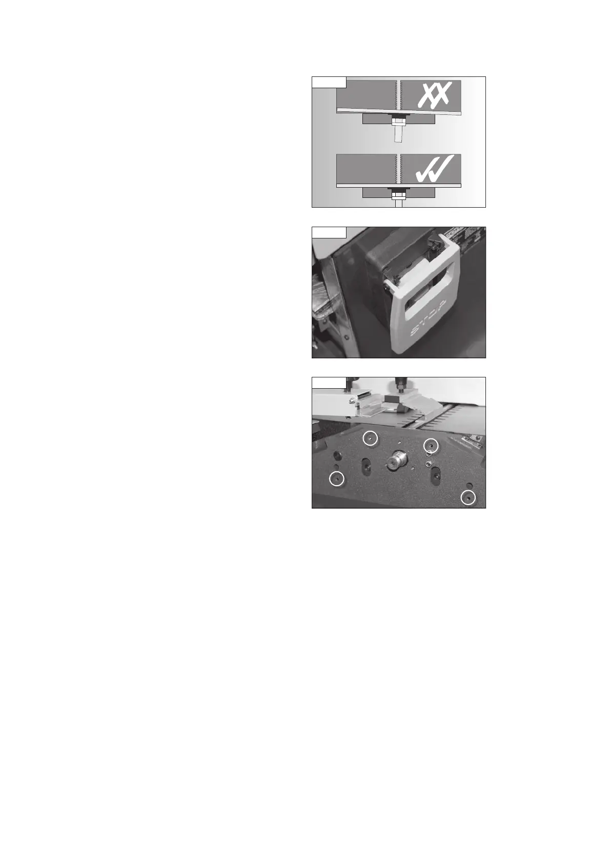
Attach the switch cover to the switch box on the front of the machine as
shown in Fig. 8.14 using the nuts and bolts supplied pre-assembled to the
switch cover.
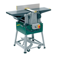
To fit the spindle cover, pass the spindle cover screws through the holes in
the cover and screw into the threaded holes on the side of the machine as
shown in Fig. 8.15.
Fig 8.14
Fig 8.15
8. Assembly
Fig 8.13
PT107 Manual 3.2.indd 14PT107 Manual 3.2.indd 14 25/04/2022 14:42:0825/04/2022 14:42:08