13
8. Assembly
Fig 8.8
Fig 8.9
Plate
Fig 8.11
Ratchet
handles
Fence
Fence
stop
Fig 8.10
Threaded holes
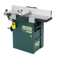
Slide the fence bracket into the carrier as shown in Fig. 8.8. The bracket can
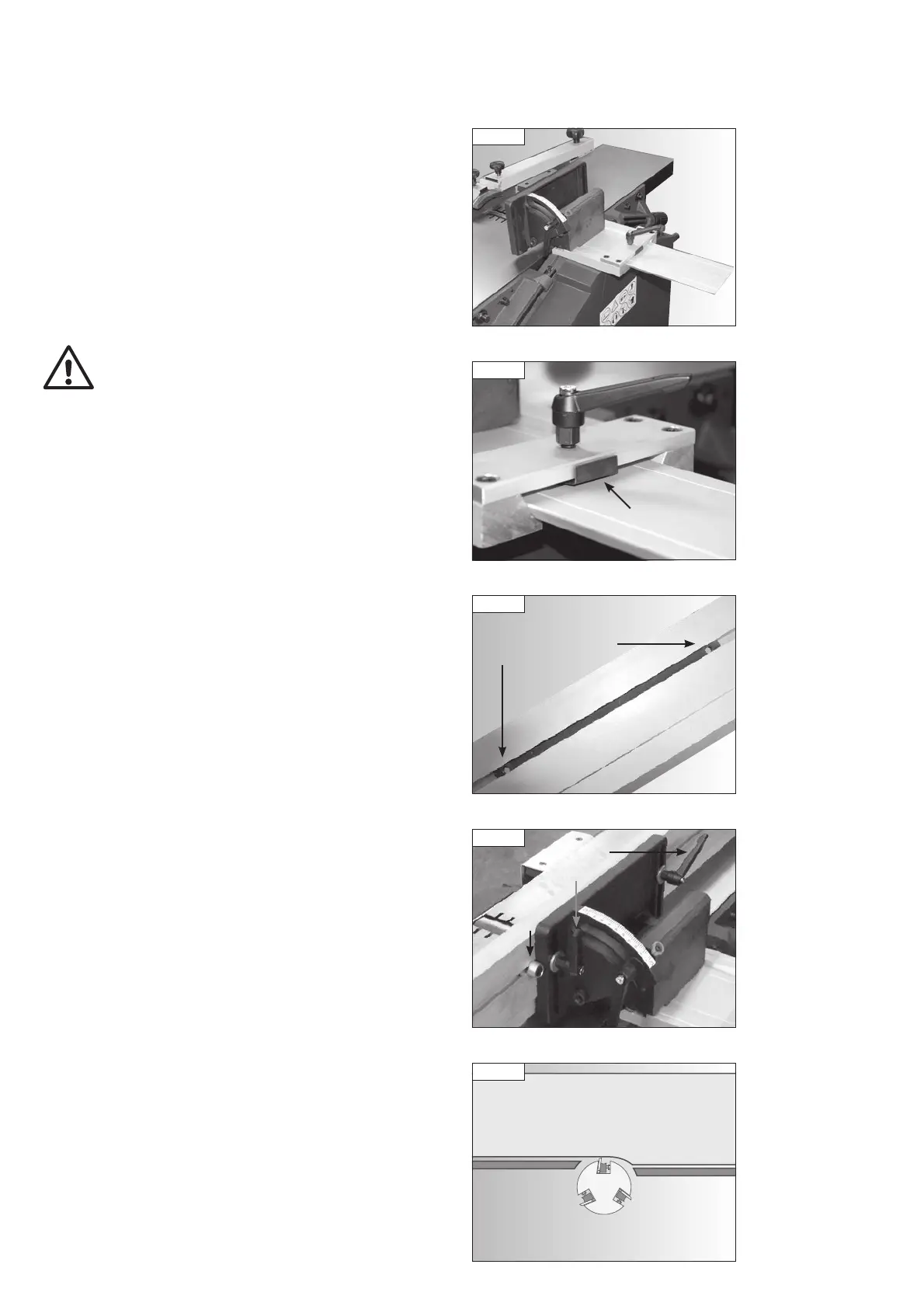
be locked in position using the locking handle of the carrier. Ensure that the
plate attached to the underside of the locking handle mount is positioned
beneath the locking handle as shown in Fig. 8.9.
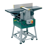
The fence features a moving plate with threaded holes inside the groove on
the rear of the fence, Fig. 8.10. Attach the fence to the bracket by screwing
the two bolts with ratchet handles attached into the holes as shown in Fig.
8.11. Ensure the washers supplied are placed between the ratchet handles
and the fence bracket as shown.
Fig 8.12
Cutter
block
Fence
Outfeed
table
Infeed
table
The fence features a stop which must always be positioned as shown in Fig.
8.11. The fence is shaped to allow maximum support to the workpiece by
having a deeper surface on its right hand side, see Fig. 8.12. The left hand
side of the fence is raised to give clearance to the outfeed table. The purpose
of the stop is to eliminate the risk of the fence being positioned so the lower
part of it comes into contact with the cutter block.
PT107 Manual 3.2.indd 13PT107 Manual 3.2.indd 13 25/04/2022 14:42:0325/04/2022 14:42:03