-30-
Drawing No. LP0932 Released 2018-01-12
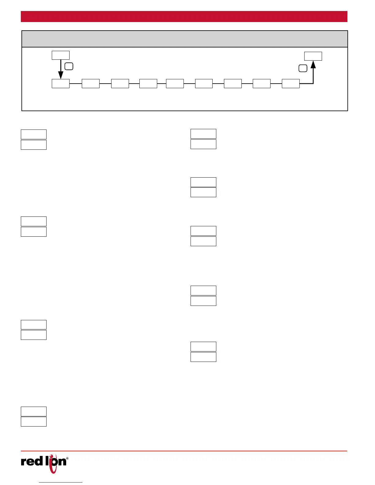
6-Pr
PROFILE
DEVIATION
ERROR VALUE
PROFILE
DEVIATION
ERROR TIME
VALUE
START-UP
RAMP RATE
PROFILE
PROFILE
ENDING
SEGMENT
y
PROFILE
SEGMENT
SETPOINT
y
PROFILE
SEGMENT
TIME
PROFILE
CYCLE
COUNT
PROFILE
LINK
P
P
Select desired profile to edit (0 thru F). When a profile is running, the
currently running segment setpoint or time value should not be changed,
however, other segments may be changed.
0 to 100.0
Profile process value conformity can be assured by using the profile
Error Value parameter. If the process value deviates outside the error
band (SP – ) while a profile is running, the controller enters the delay
mode. In the delay mode, the time base of the profile is held (delayed)
until the process value is within the deviation error band. At this time, the
profile continues running unless the process value again deviates.
These actions ensure that the actual process value conforms to the
profile.
0.0 to 999.9 minutes
When the profile enters delay mode due to the process value being
outside the Profile Error Band, a Profile Error timer starts. If the process
value remains outside the error band and the timer exceeds the Error
Time Value, the Profile Error Band Timeout flag, Pt, is set. The Alarm
output(s) can be configured to activate based on the Pt flag condition.
See 4-AL Alarm Action for more information. The flag (Pt) is cleared
when the profile is manually stopped; the profile is manually advanced
to the next segment; the profile is put into run state after being paused;
or when a profile is started. A value of 0 disables Error Band Timeout
Flag operation. See “Error Band Delay Mode Timeout” in the “Profile
Overview” section.
0.1 to 100.0 display units/minute
The Start-up Ramp Rate is used to reduce sudden shock to a process
during setpoint changes and system startup. A start-up ramp rate is used
to move the Target Setpoint at a controlled rate. The value is entered in
display units/minute. If the Ramp Rate is enabled, and the Setpoint
value is changed or the controller is powered up, the controller sets the
Target Setpoint to the current process measurement, and ramps to
setpoint. (In a properly designed and functioning system, the process
will have followed the Target Setpoint value to the Setpoint value.)
NO 0-9 and A-F
Select the last segment to be implemented within this Profile.
0 to 15
Select setpoint for profile x segment y.
0-9 and A-F
Select profile x segment y time.
Repeat the above two parameters for Px0, Ix0 thru PxF, IxF
0.0 to 999.9 minutes
Select the number of times that this Profile should repeat/cycle. Select
0 for continuous cycling.
0 to 99
Select the action that should take place when the profile has
completed the programmed number of cycles. Selection includes linking
to profile 0 thru F, end profile and continue controlling at current setpoint,
or stop output control.
0 to F Nd OP
0.0
r-V
0.0
r-
0.1
RP
NO
ProF
Nd
LINx
12
CYCx
200.0
Ixy
200.0
Pxy
15
Ndx