Installation | 17
2.7.2 LiFePO
4
SETUP
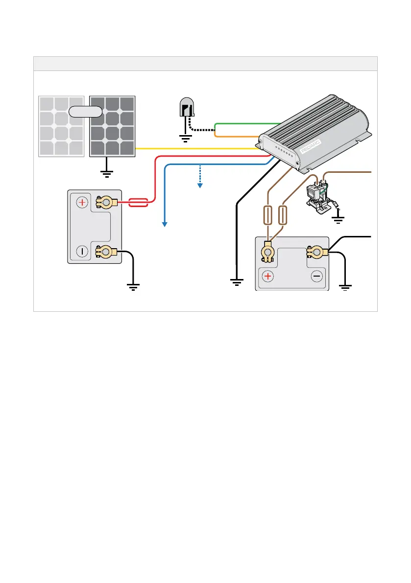
Figure 2.7.2.1: Typical LiFePO
4
Setup (12V or 24V and Solar)
12 V
Standard Trigger
Settings
Leave unconnected
or connect to Ground
12 V or 24 V
Start Battery
Bank
Fuse*
Optional
LED
Join GREEN and ORANGE
for LiFePO
4
Charging
Connect all ground
points to chassis earth
Auxiliary
Battery
Fuse*
BLACK
BROWN
Load
Fuse
Loads
Low Voltage
Disconnect
12 V Solar Panel Array
(Unregulated)***
Low Voltage
Trigger Settings
to D+ or Vehicle
Ignition**
YELLOW
RED
BLUE
GREEN
ORANGE
* Fuse Ratings to be as per the table in "Specifications" on page 6.
** To connect the Blue wire to the vehicle's ignition, connect the Blue wire to an ignition switched fuse in one of the
vehicles fuse boxes, located in either the engine compartment or vehicle cabin.
*** Do not connect regulated solar panels. If solar is not connected, tape over unused wires.