Do you have a question about the Redarc BCDC1220 and is the answer not in the manual?
Details the 6 LEDs on the front panel used to display charge profile and status.
Explains the three-stage charging process: Boost, Absorption, and Float, including automatic timeouts.
Specifies the voltage thresholds for the charger to turn ON and OFF under various conditions.
Guidance on mounting the charger in close proximity to the auxiliary battery, away from heat sources.
Provides a table for selecting appropriate wire cross-sectional area based on cable length for safe operation.
Recommends MIDI style bolt-down fuses and advises against blade fuses and self-resetting circuit breakers.
Emphasizes good, low-resistance electrical connections, recommending soldered butt splice crimps with heat-shrink.
Instructions for connecting the brown wire to the auxiliary battery positive terminal, including fuse placement.
Details connecting the black wire to a common ground point for both start and auxiliary batteries.
Explains how to connect the orange wire to set the maximum output voltage for different battery profiles.
Instructions for connecting the red wire to the positive input from the vehicle's start battery.
Details how to connect the blue wire for input trigger behaviour, depending on alternator type and vehicle ignition.
Illustrates common wiring configurations for 12V and 24V starter battery installations.
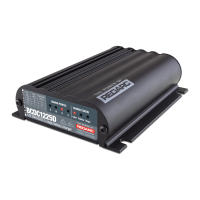
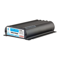
The REDARC BCDC® Dual Input Multi-Stage In-Vehicle Battery Charger is a sophisticated device designed to optimize the charging of auxiliary batteries in vehicles. It is available in two models: BCDC1220 and BCDC1220-IGN. The BCDC1220 is engineered to work with fixed voltage or temperature compensating alternators, while the BCDC1220-IGN is specifically designed for vehicles equipped with variable voltage alternators. Both models aim to ensure that your auxiliary batteries are charged to 100% capacity, regardless of their type or size, by providing a unique and appropriate charging profile for each specific battery chemistry.
The BCDC® charger operates as a three-stage, 12V, 20A DC-DC battery charger. It can accept input from either 12V or 24V nominal systems. A key feature is its ability to handle input voltages that are above, below, or equal to the output voltage, making it particularly useful for charging a 12V auxiliary battery from a 24V vehicle, or in scenarios where significant voltage drop occurs over long cable runs from the main battery. The BCDC1220-IGN model further enhances functionality by isolating the main battery from the auxiliary battery, preventing over-discharge of the main battery. This model also incorporates an ignition trigger to facilitate operation in vehicles with variable voltage or smart alternators, ensuring the charger only operates when the vehicle is running.
The charging process is divided into three distinct stages: Boost, Absorption, and Float.
The BCDC® charger includes automatic timeouts to prevent overcharging and potential damage to the battery. If a timeout occurs before the battery is fully charged, the charging process will restart from the Boost stage after a brief rest period. The device can act as both a reducer and a booster, allowing it to output a REDARC proprietary charging algorithm that is independent of the input voltage. This ensures optimal charging specific to the battery type, even if the input voltage is low due to voltage drop. The charger also incorporates the functionality of a battery isolator, turning on and initiating charging when it detects that the vehicle has started, and turning off when the vehicle is turned off. This eliminates the need for a separate battery isolator.
The charger features a user-friendly display panel with six LEDs that indicate the current charge profile and charge status.
The selection of the charge profile is managed by connecting the ORANGE wire. Leaving it disconnected sets the maximum voltage to 14.6V (Profile A). Connecting it to Common Ground sets it to 15.0V (Profile B). Connecting it to the RED wire (input source positive) sets it to 15.4V (Profile C). It is crucial to select a profile that does not exceed the battery manufacturer's recommended maximum charging voltage to prevent damage.
The input trigger settings are controlled by the BLUE wire. For a 12V alternator, the BLUE wire can be connected to the RED 'input positive' wire or directly to the vehicle ignition. For a 24V alternator, the BLUE wire must be connected to the vehicle ignition. For the BCDC1220-IGN model, designed for variable voltage or smart alternator systems, the BLUE 'input trigger' wire must always be connected to the vehicle ignition.
While the manual does not detail specific user-level maintenance tasks, it emphasizes proper installation as a key factor in the device's longevity and performance.
The BCDC® charger is designed to be a reliable and efficient solution for managing auxiliary battery charging in various vehicle setups, ensuring optimal battery health and performance through its intelligent multi-stage charging process and robust design.
| Input Voltage | 9 - 32VDC |
|---|---|
| Output Voltage | 12V DC |
| Output Current | 20A |
| Dimensions | 150mm x 120mm x 37mm |
| Weight | 0.65 kg |
| Battery Types Supported | AGM, Gel, Calcium |
| Charger Type | DC to DC |
| Protection Features | Over Temperature, Short Circuit, Reverse Polarity |