Installation | 13
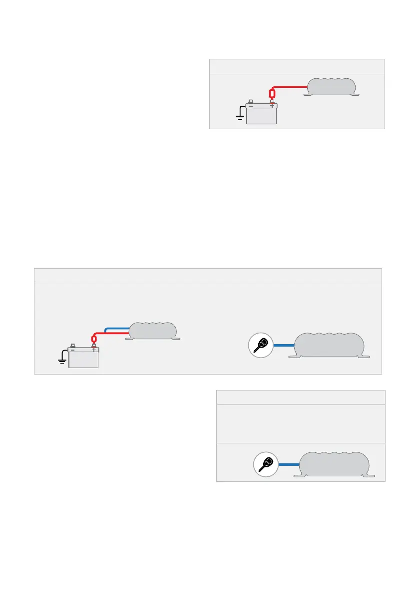
5.8 INPUT POSITIVE — RED WIRE
The RED wire should be connected to the
positive input from the vehicles start battery,
see "Specifications" on page 5 for
appropriate fuse sizes.
Figure 9: Connecting the RED wire
5.9 INPUT TRIGGER SETTINGS — BLUE WIRE
The BLUE wire is provided to select the Units input trigger behaviour, this wire must
be monitored at all times.
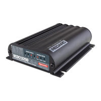
BCDC1220 BLUE WIRE CONNECTION
To charge from a 12 V alternator simply connect the BLUE 'input trigger' wire to the RED 'input
positive' wire. Alternatively, the BLUE 'input trigger' wire can be connected to the vehicle ignition.
NOTE: To charge from a 24 V alternator, the BLUE input trigger wire must be connected to the
vehicle ignition.
Figure 10: BCDC1220 BLUE wire with the
12 V Starter Battery
Connect the BLUE wire to the RED wire
12 V or 24 V Starter Battery
Connect the BLUE wire to vehicle ignition.
Vehicle
Ignition
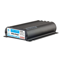
BCDC1220-IGN BLUE WIRE CONNECTION
To charge from either a 12 V or 24 V Variable
Voltage or Smart Alternator system, the BLUE
'input trigger' wire must always be connected to
the vehicle ignition.
Figure 11: BCDC1220-IGN BLUE wire
12 V or 24 V Starter Battery
Connect the BLUE wire to vehicle ignition.
Vehicle
Ignition