Installation | 9
5 INSTALLATION
5.1 INSTALL LOCATION
Mount the Battery Charger to a flat surface in close
proximity to the auxiliary battery and away from any
heat sources. The BCDC1220(-IGN) has five wires and
should be installed as described over the following
pages.
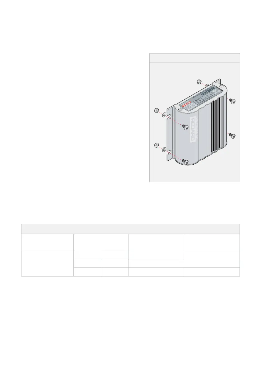
The Charger operates in any orientation (but it is
recommended that the front of the decal be visible).
Mount using the 4 mounting tabs provided on the
heatsink with suitable M6 fasteners.
NOTE: The Unit will operate optimally below 55°C
(130°F) with good airflow. At higher temperatures the
Unit will de-rate output current.
NOTE: Appropriate connections must be made to the
wires with a continuous current rating of at least 20 A
for the BCDC1220(-IGN). Failure to do so may cause
damage to the Unit and vehicle.
Figure 2: Mounting the Charger
5.2 CABLE SIZING
Below is a table outlinging the required cable size for a given cable install length. Always choose a
wire cross sectional area equal to or greater than what is specified below.
Table 2: Cable Sizing
Part Number Cable Install Length
Wire Cross
Sectional Area
Nearest Equivalent
BAE, B&S, AWG
BCDC1220 and
BCDC1220-IGN
1 – 3 m 3' – 10' ≥3.5 mm² 6 mm auto
3 – 5 m 10' – 16' ≥5.7 mm² 8B&S
5 – 9 m 16' – 30' ≥10.2 mm² 8