2 INSTALLATION GUIDE
30
AMPS
MODEL
AC INPUT
VEHICLE INPUT
SOLAR INPUT
BATTERY OUTPUT
BMS1230
230V, 50-60Hz, 560W
9 - 32VDC, 520W
9 - 32VDC, 520W
12VDC Nom./ 0-30A
Please refer to owners
manual for appropriate wire
gauge and fuse ratings.
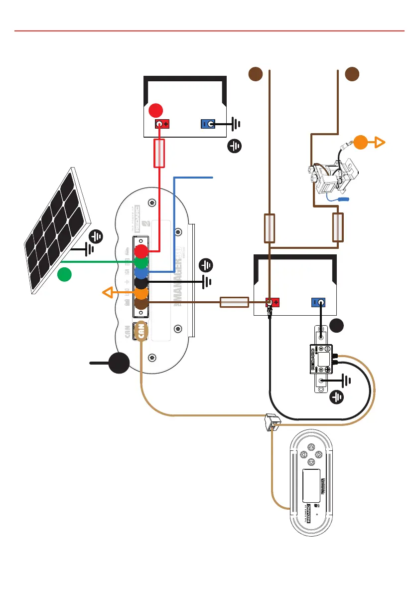
The Redarc CAN system is
designed to operate Redarc
CAN based devices only.
WARNING: Before obtaining access to terminals, all supply circuits must be disconnected
Solar
Panel
50A
Fuse
Not
supplied
Start
Battery
Essential Loads**
Remote
Monitor
BMS1230
+
+
+
Mains AC from
mains power
(rear side)
AC
MAINS
-
+
Non-essential
Loads**
House
Battery
1 2
3
4
5
6
2
Battery
Sensor
40A
Fuse
Not
supplied
Load
Fuses
Not
supplied
*
* The size of this fuse relates
to the total current draw of all
the loads connected to the
House Battery, and should be
rated slightly higher than this.
** Essential loads are loads which
must be left on at all times, until
the battery is flat. Non-essential
loads are those switched off
when the battery reaches a
particular low-charge level,
which can be set in the
‘Advanced Settings’ menu.
Ignition
Trigger
SBI12-BLD
Figure 2.4.4.2 - Typical setup.
20
 Loading...