2 INSTALLATION GUIDE
2.4.3 Connecting the Battery Sensor
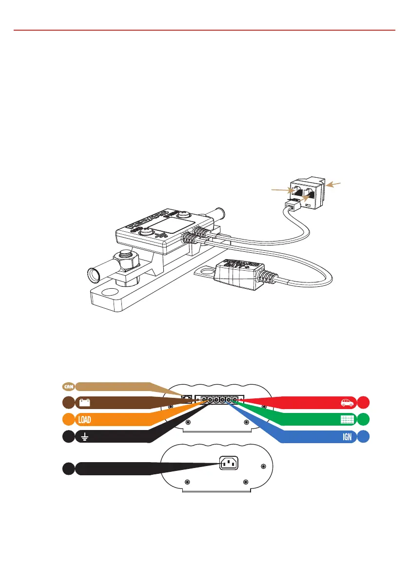
The Battery Sensor is rated for 300A Max. Wire the Battery Sensor as shown
in Figure 2.4.3.1 ensuring that the “BNEG” stud connects to the House Battery
negative terminal and the “GND” stud connects to the vehicle common ground
point. Remove the supplied RJ12 adapter* insert from the T-Piece. Connect the
CANBus Connection cable, the cable with the RJ45 connector, to the CANBus
network via the T-Piece supplied (see Figure 2.4.4.2). The Battery Positive Lead
connects to the house battery positive terminal, this lead measures voltage and
temperature at the battery.
2.4.4 Wiring the Main Unit
Refer to Figure 2.4.4.1 for required connections and to Figure 2.4.4.2 for a typical
setup.
NOTE: If a longer Remote Monitor cable is required, a replacement CAT5 patch cable may be used up to a length of 10m.
*The RJ12 adapter insert has been supplied to allow backwards compatibility with previous generation battery sensors.
to Vehicle
Common
Ground
to House Battery
Positive Terminal
to House Battery
Negative Terminal
Unit
Monitor
CAN Bus
Connection
19
CANBus Interface
Ground
1
3
5
6
Solar Input
AC Mains Input
DC Input
Battery Output
4
2
Load Disconnect
Ignition Trigger
AC
MAINS
Figure 2.4.4.1 - Required connections.
Figure 2.4.3.1 - Battery Sensor connections