www.altronics.com.au
Redback® Proudly Made In Australia 5
Redback® A 4488 Paging Console
Option 3 : One Zone Amplier using Mic or Line Level Signals and individual speakers for each zone
The audio from the paging console/s is fed down the Cat5e cable to the A 4489A audio switcher. Take the line level
(1V balanced signal) from the “Line Out” terminals or the low level balanced signal from the “Mic Out” on the rear of the
A 4489A and feed them into the audio inputs of the zone amplifer as shown in Fig 5. (Note: The Zone Amplier can be
up to a maximum of 500 Watts). The speaker output of the zone amplier is then fed into the “Audio In” terminals of the
audio switcher.
The audio from the “Zone 1” to “Zone 4” terminals are then fed directly into the speakers to provide the audio for the
four zones. The audio from these output terminals are switched internally by relays and are not present unless the zone is
activated by the paging console/s.
Background Music can be supplied to each zone by connecting a Background music amplier to the “BGM In” terminals.
Note: The background music will be present on all zones and is overidden by zone paging (see section 8.0 for more de-
tails).
7.0 General Paging
To page to a zone select the desired zone/s by pressing the buttons 1-4 or by pressing the “All Call” button if all zones are
desired. Make sure the switch is in the centre position before selecting the zones. The selected zones’ LED’s will illuminate
to indicate they have been pressed. Move the “Push to talk” switch down to the “Page” position and speak into the
microphone. Release the PTT switch when nished. The selected zones’ LED’s will ash for a few seconds after paging has
nished. While these LED’s are still ashing paging can be directed to these zones again by simply moving the PTT switch
back to the “Page” position.
If two paging consoles are connected to the system one console will be “Locked Out” when the other is in use.
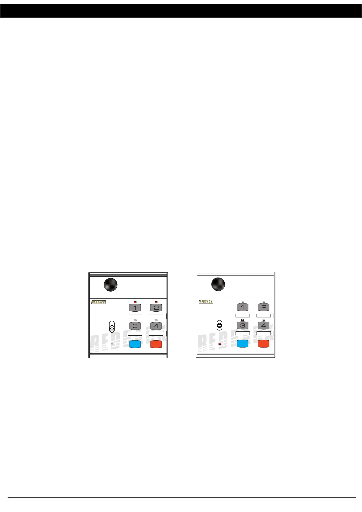
Fig 6 illustrates an example of two consoles being used together. The rst console is being used to page to zones 1 and 2.
The second console is inactive while the rst console is in use.
NOTE : If both paging consoles are tted then the ID must be set for each. See the Dip switch setting for details.
Fig 6
8.0 Connecting the BGM (Background Music)
Background music can be supplied to the paging system via one of two different methods.
8.1 BACKGROUND MUSIC (REAR OF A 4489A)
Firstly the background audio can be connected directly to the rear of the A 4489A either as a line level input as illustrated
in gure 4 or a speaker level input as illustrated in gure 5.
When using this method the background music is output to all zones until over-ridden by zone paging.
8.1 BACKGROUND MUSIC (REAR OF A 4488 PAGING CONSOLE)
The second method involves connecting an audio source (such as a mobile phone, tablet etc.) to the 3.5mm input jack on
the rear of the paging microphone as shown in Figure 7. This provides a local source of background music.
To activate the background music, rst make sure the Push to Talk (PTT) switch is in the centre position and then select
the zones to receive the background music. The selected zones LED indicators will ash to signify they have been selected.
Paging console 1 has zones 1 & 2
selected and the
“Push to Talk” switch
moved to the “Page” position.
The LED’s on zone 1 and
zone 2 are illuminated.
PAGING WITH TWO CONSOLES CONNECTED
4 Zone Communicator
System Busy
Page
BGM
All Call Cancel
A 4488
4 Zone Communicator
System Busy
Page
BGM
All Call Cancel
A 4488
Paging console 2 is
“Locked Out” because
paging console 1 is in use.
The system busy LED is
illuminated to indicate the
system is busy.
 Loading...