Reebok i-Trainer.S
08
Customer Support 0800 440 2459 Reebok i-Trainer.S
09
reebokfitness.info
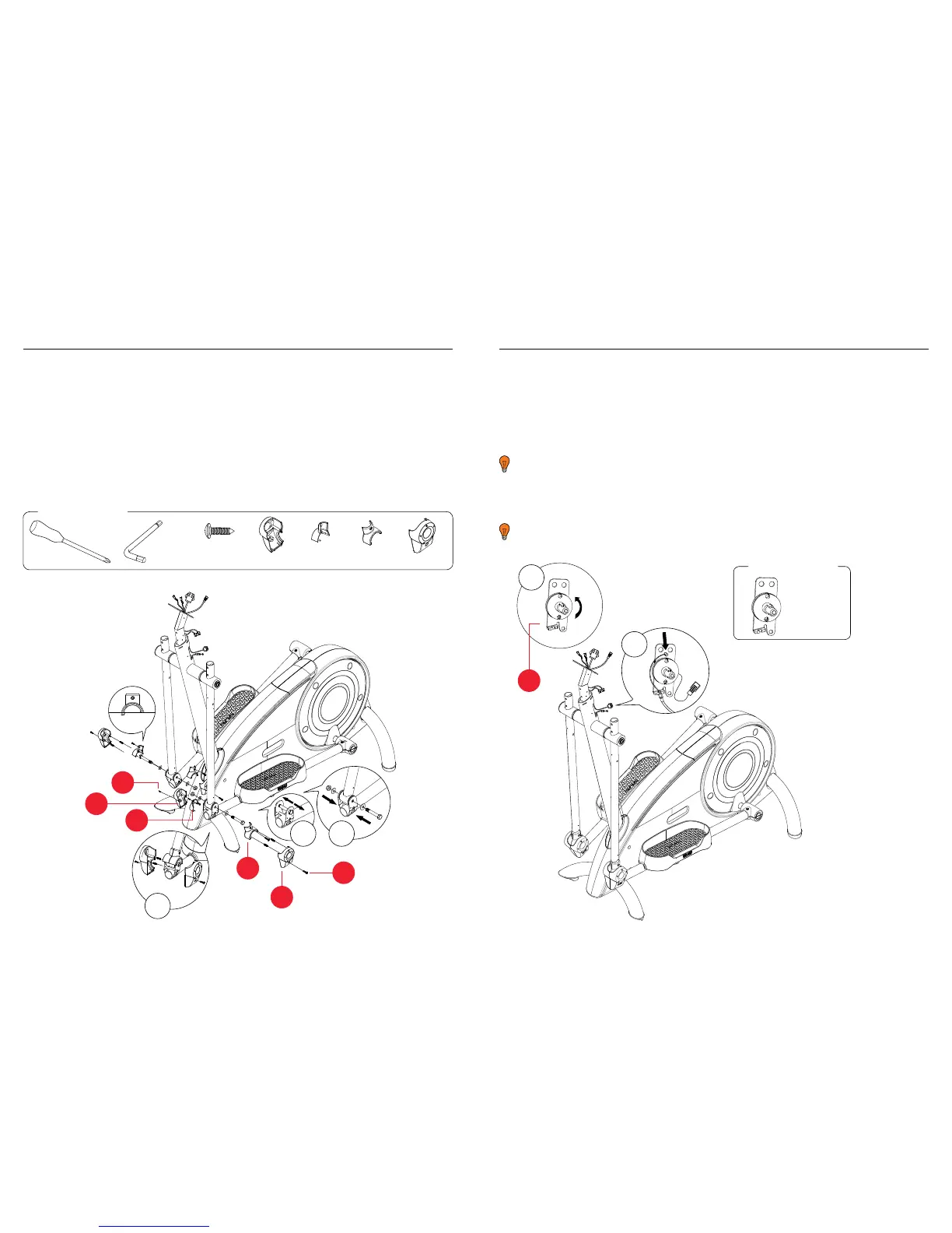
Assembly
Handles
11. Remove the nut, bolt and washers pre-assembled into the front of the pedal arm (fig.1)
12. Connect the handle to the front of the pedal arm using these components, as
illustrated (fig.2).
13. Cover the end of the handlebar by fitting the handlebar cover inners (216 & 217) to the
handlebar cover outers (712 & 713) as shown and secure using 4 x 802 screws (fig.3).
14. Repeat this process for the other handlebar.
Front
Rear
1
2
3
712
217
216
713
802
802
2
1
225
Resistance Knob
15. Rotate the white disc on the resistance knob inner (225) anticlockwise
until the notches are vertical i.e. at 12 and 6 o clock on a clock face (fig 1).
16. Connect the wire from resistance knob inner to the connecting wire
in the upright (fig 2).
You will hear a click to confirm these have connected.
17. Insert the resistance wire into the top notch onto the white disk.
18. Once inserted, pull the wire round and place the outer cable into the lower
bracket of the fixing plate, (fig.2).
You will need to pull the cable with a bit of force to mount this cable correctly.
You will require:
225 x 1
You will require:
802 x 8 712 x 2 216 x 2 217 x 2 713 x 2
5mm
RFE 4489_RE014200_iTrainerS_UMFINAL.indd 8-9 25/06/2010 15:32