Page | 6 Ascento 37 Export St Lytton QLD PH: 1800 807 604 | VSRM Inverter Contant Pressure Pumps | V2016.12
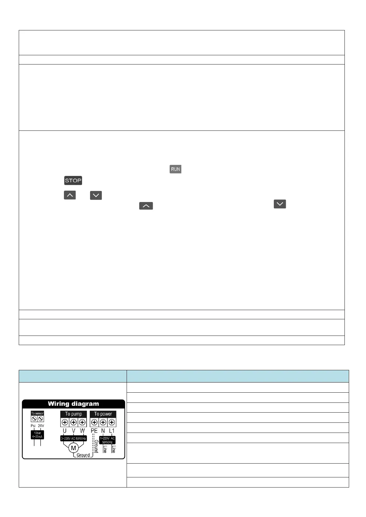
3.8 Wiring Diagram and Instruction
The pump is prewired, and any work on the wiring must only be performed by a Licenced Electrician.
Instructions for use by LICENCED ELECTRICIAN ONLY
1. Isolate the power and WAIT 5 MINUTES before opening the electrical panel.
2. Ensure wiring is correct according to the diagram. Ground = Earth
3. Make sure the power is off before wiring or servicing the unit
4. Verify the rated voltage of the inverter and the input power supply voltage is consistent.
5. Do not perform over voltage testing as this will damage the Inverter.
6. Ensure the unit is properly earthed before powering up.
7. If any cabling is changed, the new cable must be of equal or greater capacity than the cable
that was supplied from the factory. Once all parts are re-installed and checked re-connect the
input power.
8. 5. If the device will not be used for 18 months or more, the capacitors must be replaced
by a licenced Electrician, before it is used again.
9. Test for safe operation before handing over to the owner.
6. IMPORTANT: Install using Barrel-Union connections for easy removal for repair or servicing. Install a Y-Strainer or
Pre-Filter and also a Check Valve and Ball-Valve on the inlet piping. REFER to the Diagrammatic Instructions for
more information. No warranty applies if these are not fitted according to the instructions.
7. Ensure all electrical connections conform to the applicable Electrical Regulations.
8. Prime the pump - that is fill it with water so it will start;
a. Connect it to the water supply, ensuring you use the correct valves as per Diagram 1
b. Remove the bleed plug off the front of the pump (the plug is just above the water inlet part
number 12 in the diagram above.)
c. Open the ball-valve between the tank and the pump to allow the water to come through
d. Wait until the water spills out the bleed hole then re-fit the plug
e. Start the pump - if the failure light flashes, repeat the process above, until it works
9. Operating Steps
1. Connect power, the current pressure will display “00.00”bar, and the setting pressure will display the
default pressure setting which is usually 2.0bar.
2. Open a tap on the discharge side, and press to start the pump.
3. Press to stop the pump at any time.
4. Press or to check the setting pressure (the operating pressure), if you want to change the
setting pressure, press and hold to increase the pressure or press and hold to decrease the
pressure setting.
Open a tap after setting the pressure, the inverter will automatically adjust the speed control on the pump
according to the amount of water being used. Observe whether the pump is running normally, the “Current
Pressure” in the display should be fairly constant. Check the user is happy with the pressure supplied at the water
outlets, adjust the pressure up or down as required (the “Setting Pressure”). Please review IMPORTANT NOTES 1)
2) 3) & 4)
Also refer to “4.3.3 Button and Function Instruction” below.
Set the operating pressure as per “3.3 IMPORTANT NOTE” above, and “3.9.2 Button and Function Instruction”
below.
10. If the pump stops and flashes “Failure” repeat step 8. Above.
11. If the pump runs continuously without stopping, ensure the pressure is not set too high, refer to “3.3
IMPORTANT NOTE”
12. If the pump continues to run continuously refer to “3.6 IMPORTANT NOTE” above.
 Loading...