EasyManuals Logo

Reer MOSAIC MR2 Quick Installation Guide

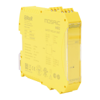
Reer MOSAIC MR2
2 pages
To Previous Page IconTo Previous Page
Page #2 background imageLoading...
Page #2 background image
MR2 / MR4
QUICK INSTALLATION GUIDE
REER S.p.A. Via Carcano 32, 10153 Torino Italia 2
Tel. +39 0112482215 r.a. Fax +39 011859867
Sito web: www.reersafety.com - email: info@reer.it
C) MORSETTIERE - TERMINAL BLOCKS - BORNIERS - ANSCHLUSSKLEMMEN - TERMINALES
PIN
SIGNAL
TYPE
DESCRIPTION
OPERATION
MR2
MR4
1
24VDC
24VDC
-
24VDC power supply
-
4
GND
GND
-
0VDC power supply
-
5
OSSD1_A
OSSD1_A
Input
Control ZONE 1
PNP active high
6
OSSD1_B
OSSD1_B
Input
7
FBK_K1_K2_1
FBK_K1_K2_1
Output
Feedback K1K2 ZONE 1
Normally closed EDM
9
A_NC1
A_NC1
Output
NC contact ZONE 1
Normally closed
10
B_NC1
B_NC1
Output
13
A_NO11
A_NO11
Output
NO1 contact ZONE 1
Normally opened
14
B_NO11
B_NO11
Output
15
A_NO12
A_NO12
Output
NO2 contact ZONE 1
Normally opened
16
B_NO12
B_NO12
Output
11
A_NC2
Output
NC contact ZONE 2
Normally closed
12
B_NC2
Output
17
OSSD2_A
Input
Control ZONE 2
PNP active high
18
OSSD2_B
Input
19
FBK_K1_K2_2
Output
Feedback K1K2 ZONE 2
Normally closed EDM
21
A_NO21
Output
NO1 contact ZONE 2
Normally opened
22
B_NO21
Output
23
A_NO22
Output
NO2 contact ZONE 2
Normally opened
24
B_NO22
Output
Warning: 2 NC contacts to control external relays FBK (terminals 7 and 19) must be connected to 24 Vdc only. Never connect
these terminals to higher voltage.
D) SCHEMA INTERNO - INTERNAL DIAGRAM - SCHÉMA INTERNE - INTERNES DIAGRAMM - DIAGRAMA INTERNO

Other manuals for Reer MOSAIC MR2

Questions and Answers:

Question and Answer IconNeed help?

Do you have a question about the Reer MOSAIC MR2 and is the answer not in the manual?

Reer MOSAIC MR2 Specifications

General IconGeneral
BrandReer
ModelMOSAIC MR2
CategoryController
LanguageEnglish

Related product manuals