EasyManuals Logo

Reer VISION VX User Manual

Reer VISION VX
40 pages
To Next Page IconTo Next Page
To Previous Page IconTo Previous Page
Page #13 background imageLoading...
Page #13 background image
12 8540571 - 25/08/2016 - Rev.15
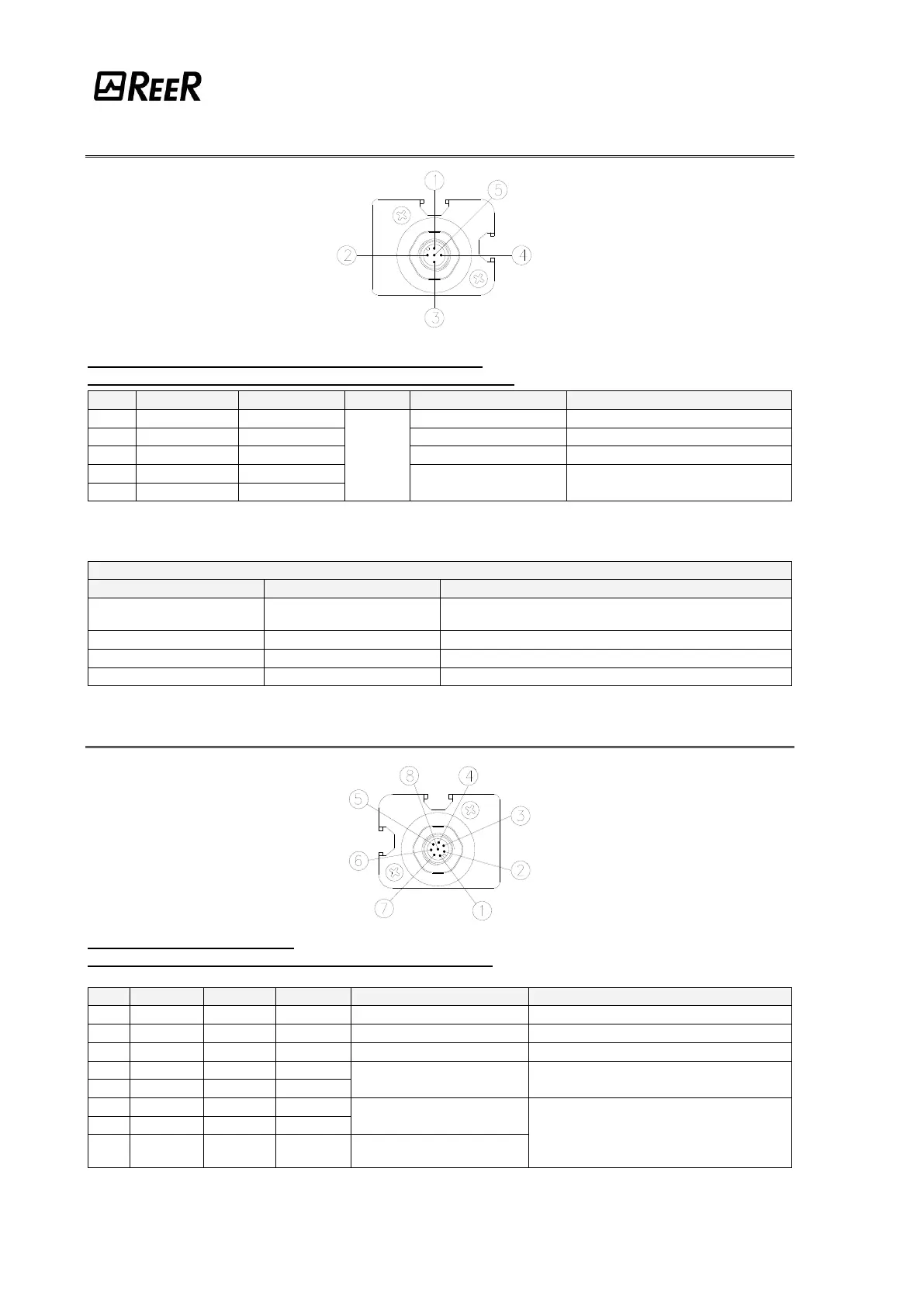
EMITTER CONNECTIONS
VX/VXM/VXS - 5 poles M12 connector (power-supply).
VXM (Master models) - 5 poles M12 Secondary connector.
PIN
COLOR
NAME
TYPE
DESCRIPTION
FUNCTIONING
1
Brown
24VDC
INPUT
+24 VDC power supply
-
3
Blue
0VDC
0 VDC power supply
-
5
Grey
PE
Ground connection
-
2
White
RANGE0*
Barrier configuration
According the normative
EN61131-2 (ref. Table 2)
4
Black
RANGE1*
* OUTPUT only on MASTER Secondary connector
Table 1
TEST and RANGE SELECTION
PIN 4
PIN 2
FUNCTIONING
24VDC
0VDC
HIGH range (1÷18m)
(3÷18 on Master/Slave) (18÷60 on Long Range)
0VDC
24VDC
LOW range (0 - 6m) (10÷22 on Long Range)
0VDC
0VDC
Emitter in test mode
24VDC
24VDC
Selection error
Table 2
RECEIVER CONNECTIONS
VX - 8 poles M12 connector.
VXM (Master models) - 8 poles M12 Primary connector.
PIN
COLOR
NAME
TYPE
DESCRIPTION
FUNCTIONING
2
Brown
24VDC
-
+24 VDC power supply
-
7
Blue
0VDC
-
0 VDC power supply
-
8
Red
PE
-
Ground connection
-
1
White
OSSD1
OUTPUT
Safety static outputs
PNP active high
3
Green
OSSD2
OUTPUT
5
Grey
SEL_A
INPUT
Barrier configuration
According the normative EN61131-2
(ref. Par. "Configuration and operation
modes" page 19)
6
Pink
SEL_B
INPUT
4
Yellow
K1_K2
INPUT
External contactors
Feedback
Table 3

Questions and Answers:

Question and Answer IconNeed help?

Do you have a question about the Reer VISION VX and is the answer not in the manual?

Reer VISION VX Specifications

General IconGeneral
BrandReer
ModelVISION VX
CategorySafety Equipment
LanguageEnglish

Related product manuals