20 8540571 - 25/08/2016 - Rev.15
K1/K2 EXTERNAL CONTACTORS CONNECTION
In every operating mode the K1/K2 external contactors feedback is activable.
If you want to use this control feature, connect the pin 4 of 8 poles M12 connector with the
power supply (+24VDC) through the series of N.C. contatcts (feedback) of external
contactors.
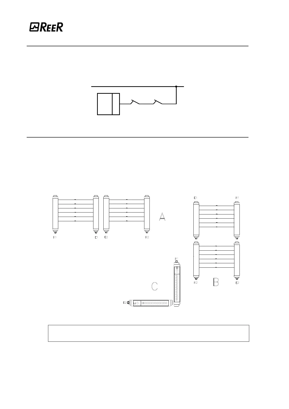
MULTIPLE SYSTEMS
When more than one VISION VX system is used, precautions must be taken to avoid optical
interference between them: install units so that the beam emitted by the Emitter of one
system can only be received by the relative Receiver.
Figure 17 illustrates some examples of correct positioning when two photoelectric systems
are installed. Incorrect positioning could generate interference, and may result in
malfunctioning.
Figure 17
This operation is not necessary in case of coexistence of a MASTER
and a SLAVE.
Systems installed alongside each other: A
Installation of two adjacent Emitters
Overlapping systems: B
L-shaped installation: C
Crossed positioning of Emitters and receivers