8540571 - 25/08/2016 - Rev.15 33
TROUBLESHOOTING
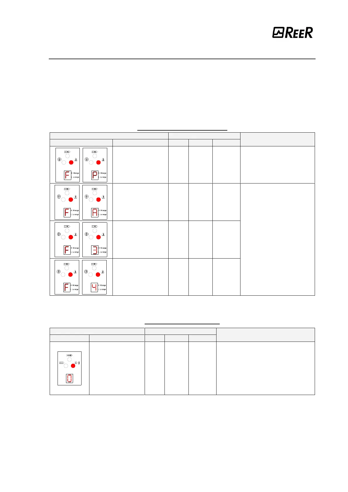
The indications provided on the displays of Emitter and Receiver make it possible to trace
the cause of a system malfunction.
As indicated in the “INDICATIONS” chapter of this manual, in the case of a fault, the system
is blocked and a "F" letter followed by a numeric code identifying the type of fault is shown
on the display of the receiver. (See the tables below).
EMITTER (BLINKING SYMBOLS)
Range selection
incorrect or modified
Carefully check the connection of
terminals 2 and 4
(EXT_RANGE0/1) on the
connector
Internal error
(add-on board)
Send the equipment for repair
to the ReeR laboratories.
Internal error
(master board)
RECEIVER (FIX SYMBOLS)
Overload of the OSSD
static outputs
Take action in one of the following ways:
(STANDARD and MASTER MODELS)
Carefully check the connection of terminals
1 and 3 (OSSD) on the connector. If
necessary, adjust load reducing the
current required to max 500 mA (2F)
(SLAVE MODELS)
Send the equipment for repair to the ReeR
laboratories.