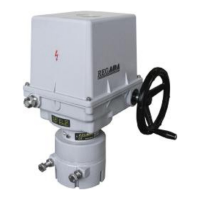
14 SP 1, SP 2, SP 2.3, SP 2.4
SPR1, SPR 2, SPR 2.3, SPR 2.4
Notes:
1. Minimum mechanical ruggedness of screws is 8G.
2. If adjustment of the position-signaling unit, the transmitter or the position indicator in the production plant do
not correspond with the EA connected this way, adjust the units. If adjustment of the stop ends was
changed, it is needed to adjust the stop end screws again.
• In the end of mechanical connection check correctness of the connection with the valve/gearing with
rotating the handwheel.
3.1.2 Electric connection and checking of function
Follow up with connecting the EA with mains or master system.
1. Follow instructions in the part "Requirements for professional qualification"!
2. While laying electrical line abide by the instructions for heavy current installations.
3. Cables to terminal boards or connectors lead through cable glands. The cable jacket diameters must
conform to the extent specified in Chapter 2.2.2!
4. Before initiation ES into operation internal and external protection terminals are needed to be
connected.
5. Feeding cables are to be fixed to the solid construction at most 150 mm from the cable glands.
6. To prevent moisture from entering the actuator around the connecting cables, the cables must be sealed with
silicone material at the point of penetration through device shell.
Connecting with the master system:
The EA can be controlled with:
• a built-in position controller
• an external position controller
1. If the EA is controlled with an external controller using unified signal from a two- wire transmitter
(capacitive or resistive with a converter in two-wire connection), it is needed to arrange connecting of
the two-wire transmitter loop to electrical earth of the successive external controller!
2. Connection can be performed only in one point, in any part of loop out of the EA.
3. Electronics of the two-wire transmitters is galvanically insulated that is why it can serve as an
external source for supplying of several transmitters (their number depends on current which the
source can supply).
Connecting to terminal board
• Check whether the type of current, supply voltage and frequency correspond with data on the nameplate of
electric motor.
• Remove the upper cover.
• In case of the single-phase version the phase L1 and the lead N connect to the corresponding terminals. In
case of the three-phase version connect the phase cables L1, L2 and L3 to U, V, W (terminals 2, 3, 4), the
protection cables to the marked places of internal and external protection terminals.
For operating of armature without stop ends is needed to connect the positional switches S3, S4 to the power
supply of electric motor before S1, S2.
• Connect the control cables according to the wiring diagram placed into the internal side of the cover.
• Put the cover on and tighten it uniformly crosswisely.
• Tighten the cable cable glands firmly to assure the protection enclosure rate.
Connection to connector:
• Check whether the type of current, supply voltage and frequency correspond with data on the nameplate of
electric motor.
• Release the connectors shells;
• Insulate the ends of conductors;
• Connect the appropriate sleeve connector by means of recommended pliers;
• Insert the sleeves into appropriate connector contacts according to connecting wiring diagrams.
• Fix the connectors and tighten them;
• Tighten the cable cable glands firmly to assure the protection enclosure rate.
!
!

 Loading...