18 SP 1, SP 2, SP 2.3, SP 2.4
SPR1, SPR 2, SPR 2.3, SPR 2.4
Note:
The output signal of 4-20mA can be adjusted at the range from 75 up to 100% of the rated stroke stated on the
actuator′s nameplate. At values less than 75% the value 20mA is reduced proportionally.
Adjustment of the EPV in Electric Actuators SPR with controllers
• Disconnect the circuit with removing a jumper on the terminals 81 and 82.
• Disconnect the control signal from the terminals 86/87 and 88.
• Set the actuator to the direction ”OPENING” or “CLOSING” with the handwheel, or with connecting power to
the terminals 1 and 20 for the direction “OPENING” or 1 and 24 for the direction “CLOSING”.
• Set the actuator to the position “CLOSING“ and switch the converter off on the terminals 1 a 61.
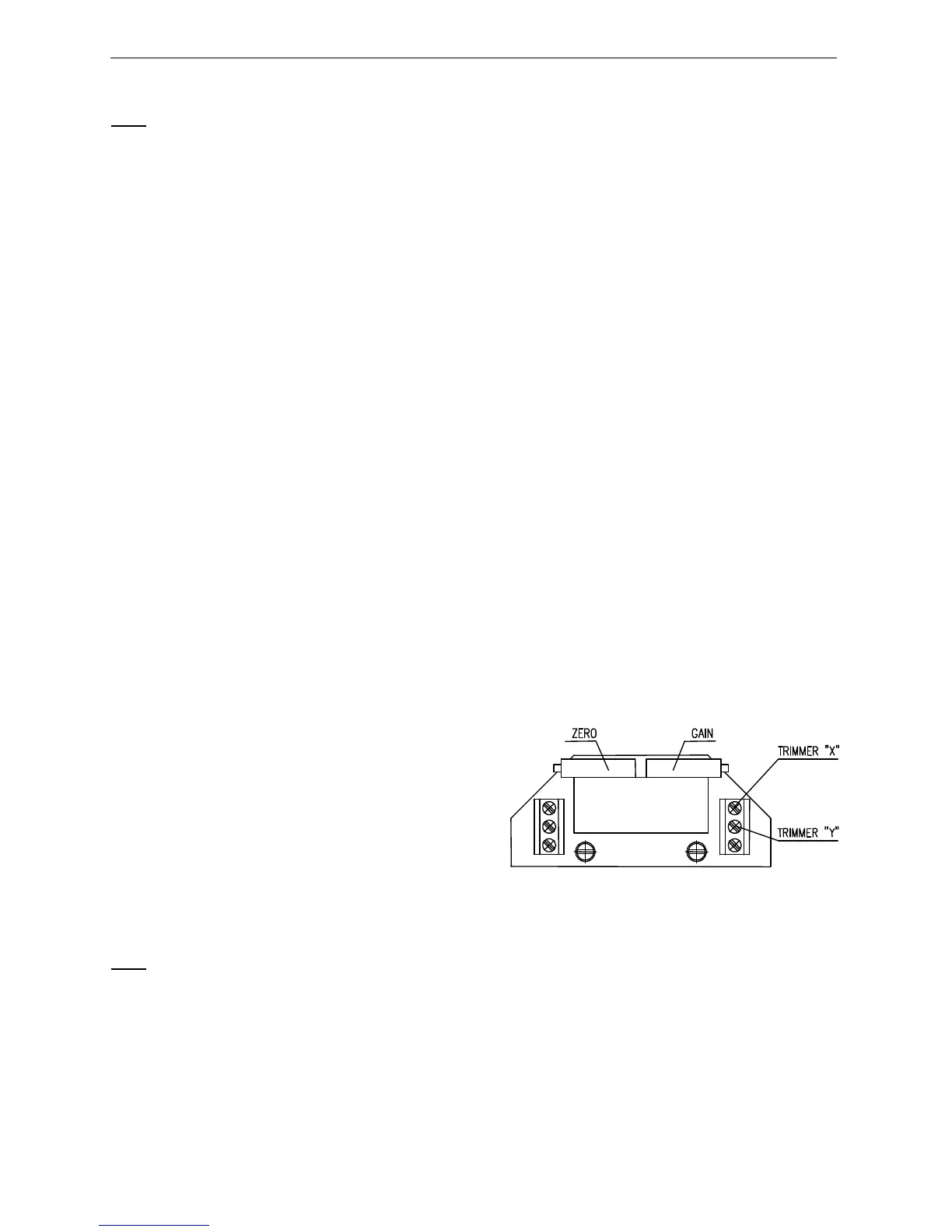
• Adjust the resistive transmitter according to the previous chapter. The resistance is to be metered on the
terminals X-Y (Fig. 6).
• Connect power supply to the terminals 1 and 61.
• Turn the adjusting trimmer ZERO (Fig. 6) to adjust the output current signal rate measured on the terminals
81-82 to 4mA.
• Set the actuator to the position “open”.
• Turn the adjusting trimmer GAIN (Fig. 6) to adjust the output current signal rate measured on the terminals
81-82 to 20mA.
• Check the output signal of the converter in the both limit positions, and repeat the procedure if needed.
• Having the transmitter adjusted put the jumper again on the terminals 81 and 82 in case that the output
signal wont be used (the circuit through the terminals 81 and 82 should be closed).
• Connect the control signal to the terminals 86/87 and 88.
4.4.2 EPV – 3-wire version (Fig. 7)
The resistive transmitter with the converter is in the plant adjusted to have the output current signal
metered on the terminals 81-82 as follows:
• in the position ”open” ............................................20 mA or 5 mA
• in the position ”closed” ..........................................0 mA or 4 mA
according to the specified version of the converter.
If the transmitter requires a new adjustment follow these steps:
• Put the actuator to the position ”closed” and switch the power supply off.
• Adjust the resistive transmitter according to the previous chapter. The resistance is to be metered on the
terminals X-Y (Fig. 6). The used transmitter resistance
is 2000 Ω or 100 Ω.
• Switch the converter′s power supply on.
• Turn the adjusting trimmer ZERO (Fig. 7) to adjust the
output current signal rate measured on the terminals
81-82 to 0 mA or 4mA.
• Set the actuator to the position ”open“.
• Turn the adjusting trimmer GAIN (Fig. 7) to adjust the
output current signal rate measured on the terminals
81-82 to 20mA or 5 mA.
• Check the output signal of the converter in the both
limit positions, and repeat the procedure if needed.
Note:
The output signal of (0-20mA, 4-20mA or 0-5mA - according to the specification) can be adjusted at the range
from 85 up to 100% of the rated stroke stated on the actuator′s nameplate. At values less than 85% the value of
the output signal is reduced proportionally.
[Fig. 7]