TT-S4/D
1877G APR 19
Box 116
428 22 KÅLLERED SWEDEN
Tel +46 (0)31 720 02 00 Fax +46 (0)31 720 02 50
4
INSTRUCTION INSTRUCTION
Function
On an increasing input signal TT-S4/D will rst increase the 0 - 10V
output signal. If the power demand becomes so large that the output
signal would need to be larger than 10V, the TT-S4/D will activate
the rst relay. The output is held at 0V for 10 seconds and is then
set to an output corresponding to the part of the output signal that
would have been larger than 10V.
In order to get the best control possible the TT-S4/D automatically
sets the amplication between the input signal and the output signal
to suit the maximum number of relay outputs used. At an input signal
of 10V the number of relays set on the rotary switch will be activated
and the output signal will be at 10V.
TT-S4/D will only increase or decrease the relay outputs one at a
time with a time delay of 10 seconds between steps. Change of
direction i.e. from increasing power demand to decreasing power
demand or vice versa is delayed 30 seconds to minimize the risk of
unwanted instability.
Test function
Turn o the supply voltage to TT-S4/D and set the rotary switch to
position 0. Set the Binary/Sequential switch to the position suited to
the heater on hand.
Reconnect the supply voltage.
All relays should now be deactivated and the output signal equal to
0V.
N.B. It is normal for the LEDs to wink faintly even when they are
unactivated.
By twisting the rotary switch clockwise the relays are activated in
sequence and the output signal on terminal 19 will increase from 0
when the switch is in position 0, to 10V when the switch is in posi-
tion 15 for binary mode, or 4 and above for sequential mode.
N.B. Upon completion of the test function:
• Turn the supply voltage to the TT-S4/D o.
• Set the switches to positions suitable for the installation.
• Reconnect the supply voltage.
If this is not done, the TT-S4/D will remain in test mode.
CE information
This product carries the CE-mark. For more information, see
www.regincontrols.com.
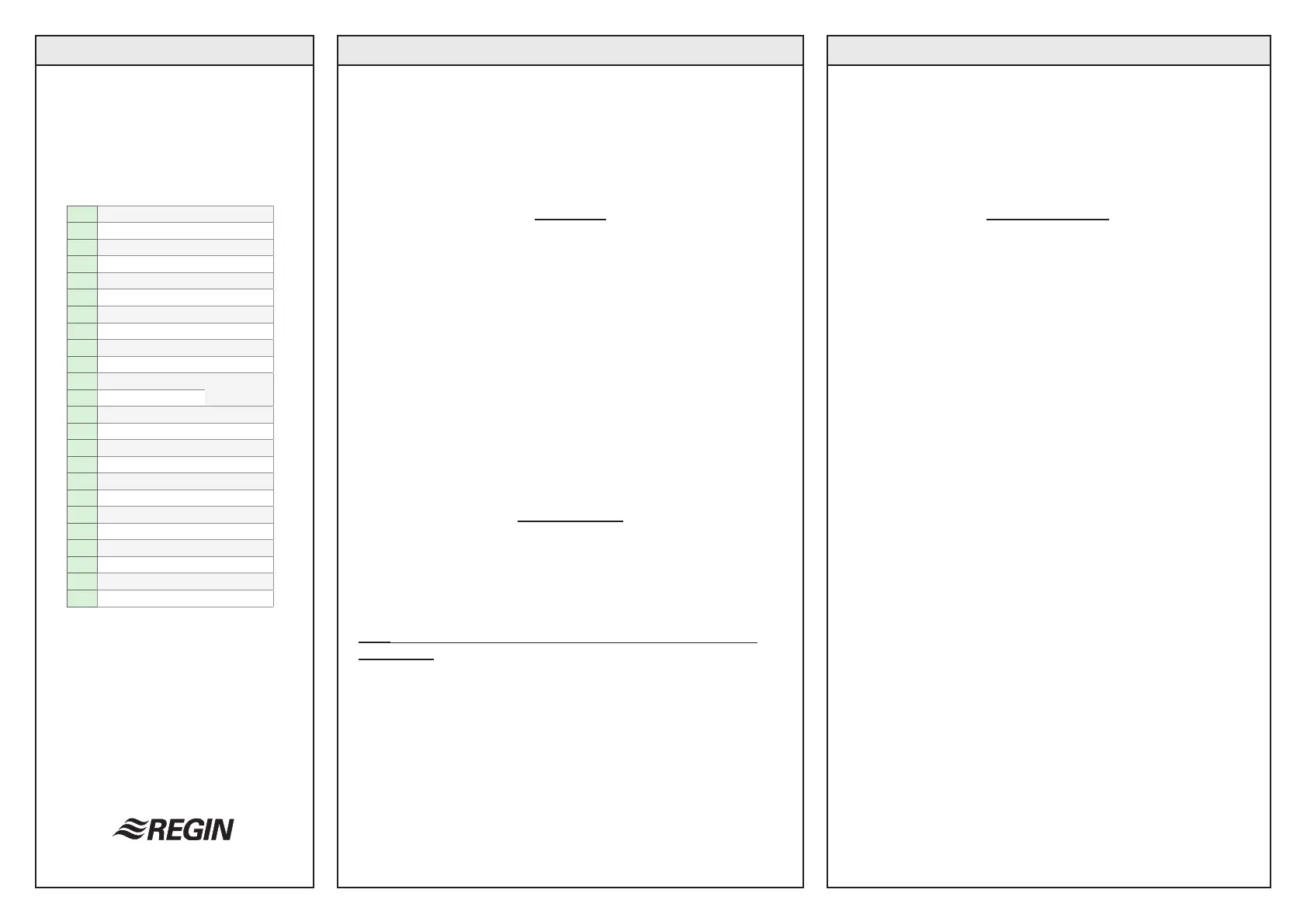
1 Relay 1 out
2 Relay 2 out
3 Relay 3 out
4 Relay 4 out
5 Not connected
6 Relays 1-4 common in
7 Not connected
8 Not connected
9 Not connected
10 Not connected
11 24 V AC in Supply
voltage
12 Neutral
13 0...10 V DC input
14 Signal converter, 10...2 V DC in
15 Signal neutral
16 Not connected
17 Not connected
18 Not connected
19 0...10 V DC output
20 Signal converter, 0...10 V DC out
21 Signal neutral
22 Not connected
23 Not connected
24 Not connected
 Loading...