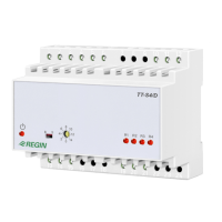
TT-S4/D
1877G APR 19
Box 116
428 22 KÅLLERED SWEDEN
Tel +46 (0)31 720 02 00 Fax +46 (0)31 720 02 50
3
INSTRUCTION INSTRUCTION
Step controller for electric heating
TT-S4/D is a microprocessor-based step controller designed for use
together with Regin’s TTC controllers. It has a control input signal
of 0 - 10V DC. It has four relay outputs for controlling four heater
groups. The TT-S4/D can be set to control either a heater with equal
loads giving 4 steps, or a heater where the load is binary divided
giving 15 steps. The TT-S4/D also has a 0 - 10V DC output for
controlling a triac controller for smoothing the power output between
the relay steps. The maximum number of relay steps can be limited
using a switch on the front.
TT-S4/D has a built in test program for simple function testing.
TT-S4/D is built for DIN-rail mounting with all settings accessible on
the front.
Installation
Mount the TT-S4/D on a DIN-rail in a cabinet or other enclosure.
Protection class: IP20.
Ambient temperature: 0 - 50°C.
Wiring
Supply voltage
Supply voltage: 24V AC +/-15% 50-60Hz.
Power consumption: 6 VA.
Terminal 11 = Phase.
Terminal 12 = Neutral.
Control input
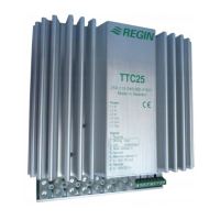
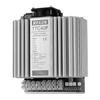
Control voltage 0 - 10V DC from a TTC25, TTC40F or TTC80F con-
troller, or other controller with a 0 - 10V input.
Terminal 13 = 0 - 10V DC input.
Terminal 15 = Signal neutral.
Control output
The control output is used to control a triac controller that will give
0 - 100% power between each relay step. The load connected to the
triac controller should have the same size as the load connected to
relay 1.
TT-S4/D automatically adjusts the ratio between the input signal
and the output signal according to the setting of the maximum step
switch.
Terminal 19 = 0 - 10V DC output.
Terminal 21 = Signal neutral.
Relay outputs
Relays 1 - 4, SPST with a common supply pole. 240V AC 2A
total.
When the heater is binary divided the loads must be wired in
rising size with the smallest load on relay 1.
Terminal 6 = Common relay input 2A 250V AC.
Terminal 1 = Relay 1 output.
Terminal 2 = Relay 2 output.
Terminal 3 = Relay 3 output.
Terminal 4 = Relay 4 output.
N.B. The supply to terminal 6 must be wired so that the power
is cut in the event of the fan motor relay or the heater high-limit
switch tripping.
Signal converter
TT-S4/D contains a signal converter that converts a 10 - 2V DC
input signal to a 0 - 10V DC output signal.
This is used when TT-S4/D is controlled by for example TA-con-
trollers with a 10 - 2V DC output.
Terminal 14 = 10 - 2V DC input
Terminal 20 = 0 - 10V DC output, connect to terminal 13.
Settings
Binary - Sequential switch
Set to S if all the load is divided into equal parts.
Set to B if the load is binary divided, i.e. if the parts have the
size-ratio of 1:2:4:8.
Maximum number of permitted relay steps
With the rotary switch you set the maximum number of relay
steps to be used.
To ensure correct control it is important that the switch is correct-
ly set. During sequential control (S), all positions > 4 correspond
to a maximum of 4 relay steps being connected. Position 0 is the
starting position for the built-in test function.
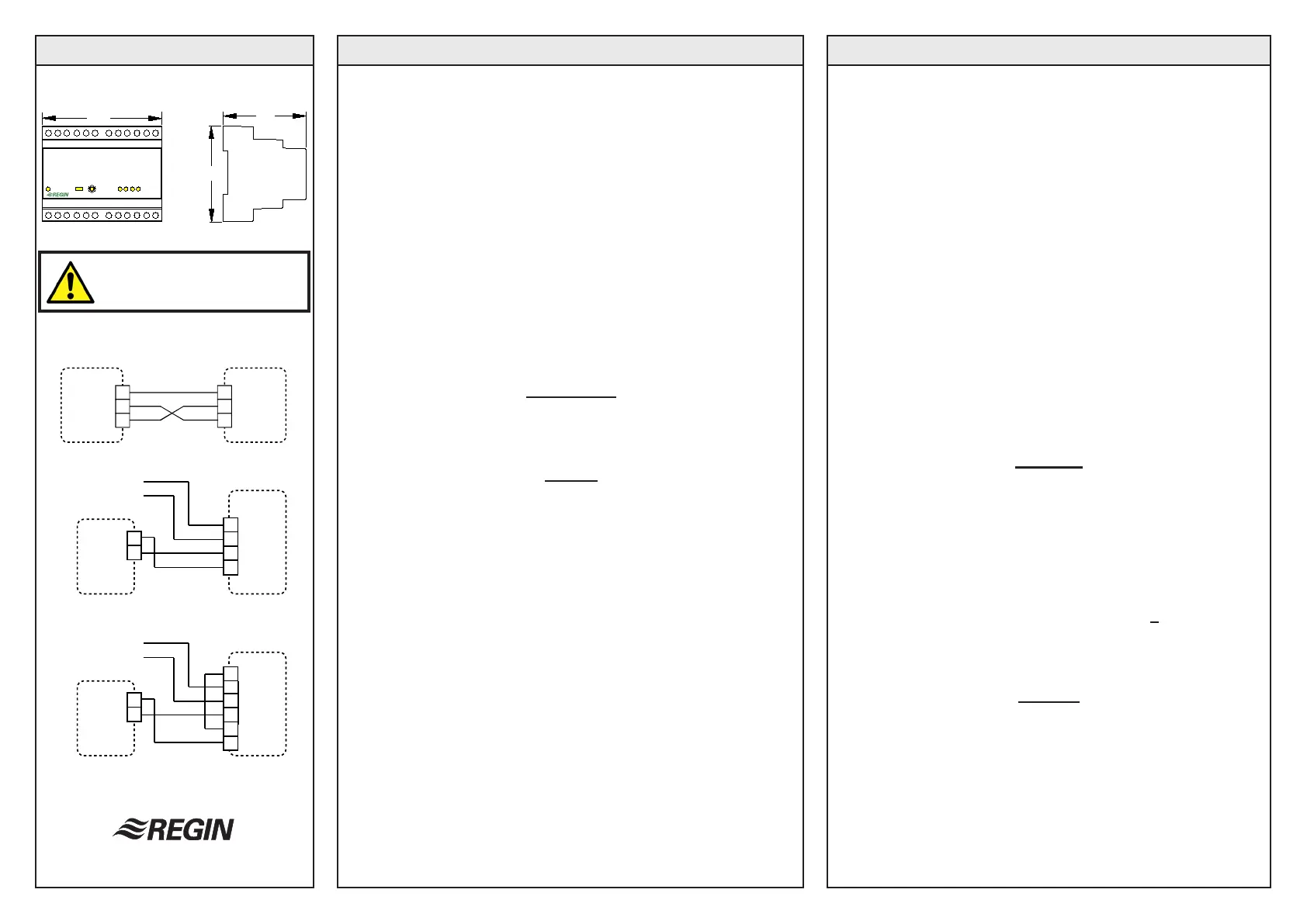
Figures
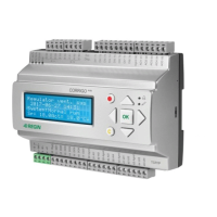
Fig 1: Wiring of TTC25/TTC40F/TTC80F when the system is
controlled by a sensor connected to TTC25/TTC40F/
TTC80F
Fig 2: Wiring of TTC25/TTC40F/TTC80F and 0...10V DC
control signal from an external source.
Fig 3: Wiring of TTC25/TTC40F/TTC80F and 10...2V DC
control signal from an external source.
IMPORTANT: Read these in-
structions before installation and
wiring of the product.
101
74
85
TT-S4/D
TTC25
TTC40F
TTC80F
TT-S4/D
8
9
+
0
0...10 V DC in
13
15
19
21
TT-S4/D
8
9
+
0
10...2 V DC in
13
15
19
21
14
20
TTC25
TTC40F
TTC80F
TTC25
TTC40F
TTC80F
TT-S4/D
7
8
9
13
19
21
Fig 1
Fig 2
Fig 3
 Loading...