Read this instruction before installation
and wiring of the product
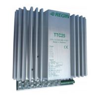
TTC25
Consult documentation in all cases where this symbol
is used, in order to nd out the nature of the potential
hazards and any actions to be taken
1
TTC25
Triac controller for proportional control
of electric heating
TTC25 is a proportional controller for electric heating with automatic
voltage adaption. TTC25 pulses the whole load On - Off. The ratio
between On-time and Off-time is varied 0 - 100% to suit the prevailing
heat demand. The current is always switched at zero phase angle to
prevent RFI.
TTC25 can control both symmetrical Y-connected 3-phase heaters
and symmetrical or asymmetrical Delta-connected heaters.
TTC25 is only intended for electric heating control. The control
principle makes it unsuitable for motor- or lighting control.
TTC25 is intended for DIN-rail mounting.
Installation
Mount TTC25 on a DIN-rail in a cabinet or other enclosure.
Mount TTC25 vertically with the text right side up.
Protection class: IP20.
Ambien temperature: 0 - 40°C
N.B. TTC25 emits approx. 45W of heat at full output which must be
dissipated.
Wiring
Supply voltage
Terminals L1in, L2in and L3in.
Supply voltage: 210-255 or 380-415V AC
3 phase, 50 - 60 Hz with automatic voltage adaption.
Maximum current 25A/phase.
N.B. The supply voltage to TTC25 should be wired via an all-pole switch
with a minimum contact gap of 3mm.
N.B. TTC25 must be earthed.
1
1
1
3
2 3
4 5 6
7
8
9
L1
L2
L3
L3
L2
L1
Figure 1: Wiring of supply voltage and load
Load
Terminals L1out, L2out and L3out.
Resistive 3-phase heater without neutral.
Maximum load: 3300W/phase at 230V phase - phase voltage (25A).
5750W/phase at 400V phase - phase voltage (25A).
Minimum load: 530W/phase at 230V phase - phase voltage (4A).
920W/phase at 400V phase - phase voltage (4A).
Main sensor and external setpoint (gs 2-6)
Terminals 1 and 4. Low voltage. Not polarity sensitive.
N.B. Terminals 2 and 3 are internally connected and are used to simplify
wiring when using external setpoint.
N.B. Choice of internal or external setpoint is made using switch 1.
1777F
FEB 14
EN
12
3
2
TG-K3xx
TG-G1xx
TG-R4xx
3 4
12
2
1
TG-K3xx
TG-G1xx
TBI-xx
3
4
Figure 6: Wiring of external, separate sensor when using
potentiometer TBI-xx as external setpoint
Figure 2: Wiring of room sensor TG-R530 or TG-R6xx
when using internal setpoint
Figure 3: Wiring of room sensor TG-R430 used as external
setpoint and sensor
Figure 4: Wiring of oor or duct sensor when using
internal setpoint
Figure 5: Wiring of external separate sensor when using TG-R4xx
as external setpoint
1 2
2
1
TG-R5xx
TG-R3xx
3
4
1 2
3
1
TG-R4xx
3 4

 Loading...