93
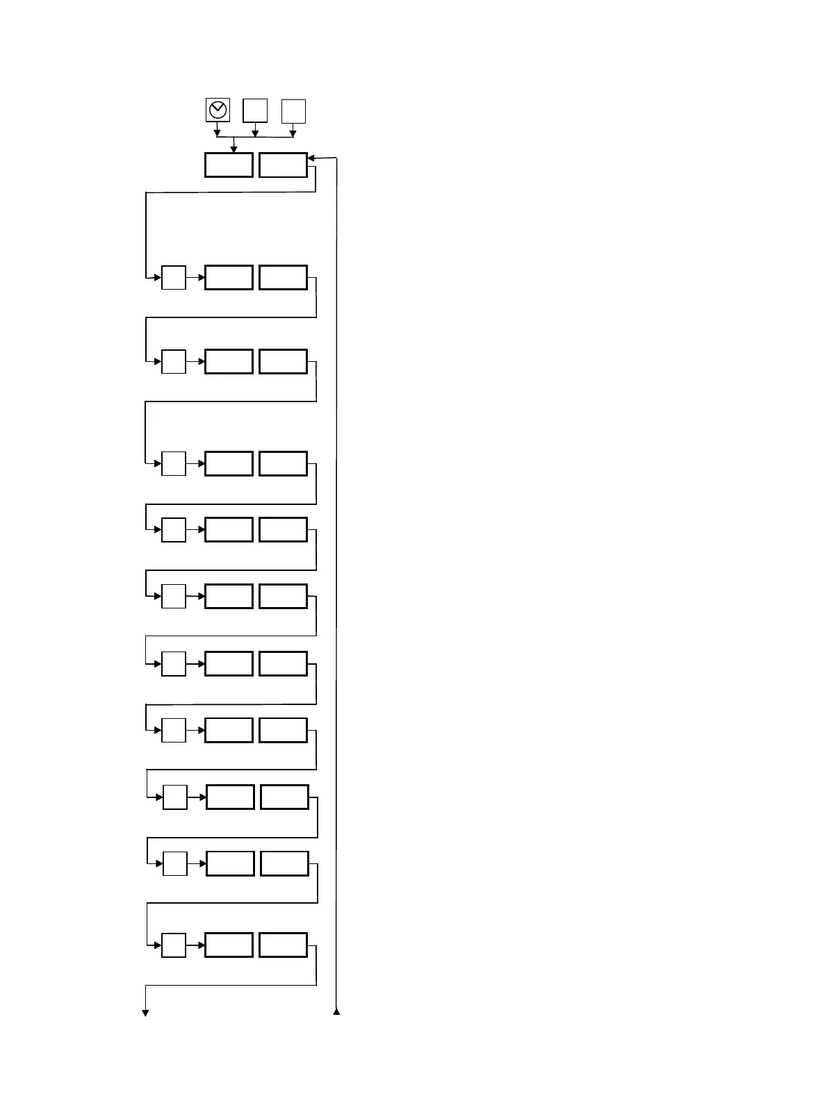
7.6 System Level “SEt SyS”
For programming functions and defining hardware.
This level can be reached by pressing the key with the timer
symbol 3 times while pressing the “∆” and “∇” keys.
The desired setting can be achieved by pressing the “∆”
and “∇” keys.
To move backwards:
press the “P” key for a maximum of 2 s.
To return to the operating level with display of the set and
actual values from any desired display, press the “P” key for
3 s.
“yES” After a power failure, the unit will continue to func-
tion as it did prior to failure.
“no” After a power failure, the unit will remain switched
off.
“yES” An incorrect phase sequence will be corrected auto-
matically.
“no” An incorrect phase sequence will not be not correct-
ed automatically. “PHA SE” will appear.
Pump current in A.
Type of external sensor Sn2. CA = K (NiCr-Ni).
FE = J (Fe-CuNi). Pt = Pt100. Cu = T (Cu-CuNi).
Type of third sensor Sn3. Pt = Pt100.
Appears only if present.
Pu: suction with pump.
Alr: blow out with compressed air.
Max. possible run-down time of the pump before the
change in direction of rotation in suction or leak-stop mode
in s.
Run-out time of the pump in s after “Level 1” alarm is
tripped.
Level alarm suppression in minutes. 0 = Function off. After
switching on by means of the main switch the heat transfer
fluid can be added as often as desired during the time pe-
riod set.
Delay time in seconds before the pressure-relief valve Y8
opens. 0 = No delay.
Appears only if H2O = yES (→ SEt Fun, Section 7.2).
P
P.on yES
yES/no
P
A.Ph yES
yES/no
P
PU 0.1
0.1...16.0
P
Sn2 Pt
Pt/FE/CA/
Cu
P
Sn3 Pt
Pt
P
dtr ...
0...9
SEt SyS
∆
∇
P
Suc ...
Pu/Alr
P
dtP ...
3...30
P
rtP ...
0...20
P
dtL ...
0...15
++
3 x
P
PU 0.1
0.1 to 16.0
P
Sn2 Pt
CA/FE/Pt/Cu
P
Sn3 Pt
Pt
P
dtr ...
0 to 9
P
Suc ...
Pu/Alr
P
dtP ...
3 to 30
P
rtP ...
0 to 20
P
dtL ...
0 to 15