Do you have a question about the REMEHA Sol Plus and is the answer not in the manual?
Detailed technical specifications for the Sol Plus solar controller, including inputs, outputs, power, and dimensions.
Step-by-step guide for physically mounting the Sol Plus controller onto a wall.
Instructions for safely connecting the Sol Plus controller to the electrical supply and system.
Details on the PWM outputs used for speed control of pumps, including terminal assignments.
Information on VBus® and ModBus data transfer capabilities for connecting external modules and PCs.
Visual diagrams and descriptions of various solar system configurations supported by the controller.
Description of different system arrangements, from standard solar systems to those with backup heating.
Explanation of how the SOLARFIRST function prioritizes solar heat for DHW heating by signaling the boiler.
Describes the function of the three buttons for navigating menus and adjusting settings.
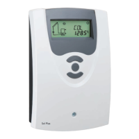
Explains the controller's display, including channel display, tool bar, and system screen.
Details on status symbols and flashing codes used to indicate system states and errors.
Guide to the initial setup process, including language, temperature unit, time, and system selection.
Adjusting the maximum allowable temperature for the store to prevent overheating.
Configuring the operating mode for pumps (OnOF, PULS, PSOL, PHEA).
Description and purpose of various display channels showing system status and data.
Information on how collector, store, and sensor temperatures are displayed on the controller.
Details on displaying flow rate, pump speed, and accumulated heat quantity (kWh/MWh).
How to identify and interpret error codes displayed on the controller for fault diagnosis.
Steps to diagnose and resolve issues when the controller display is not working.
Causes and solutions for the solar pump starting later than expected.
Addressing issues where the pump cycles on and off erratically.
Solutions for situations where the collector cannot dissipate heat effectively.
Information on high-precision platinum temperature sensors and overvoltage protection.
Protection device to prevent damage to collector sensors from lightning.
Displays (SD3, GA3), Alarm Module (AM1), and Dataloggers (DL2, DL3) for system monitoring.
Adapters for connecting to PCs via USB or LAN for data transfer and parameterization.
| Power Supply | 230 V AC, 50 Hz |
|---|---|
| Display | LCD |
| Type | Controller |
| Operating Temperature | 0 °C to +50 °C |
| Buttons | 4 |