en
9
InstallationIndications, functions and optionsMessages Commissioning Operation and function
2.6 Systems
S1
S2
S4 / TR
R1
S3 / TSTT
S1
S3
S2
R1 R2
exemplary
drainback system layout
(with booster pump)
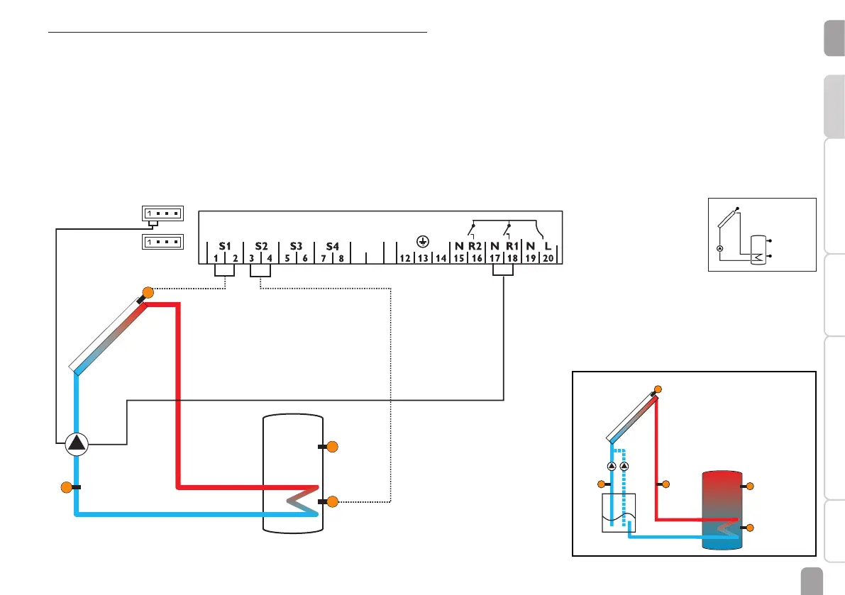
Arrangement 1: Standard solar system
The controller calculates the temperature difference between collector sensor S1
and store sensor S2. If the difference is larger than or identical to the adjusted
switch-on temperature difference (DT O), the solar pump will be activated by relay
1, and the store will be loaded until the switch-off temperature difference (DT F) or
the maximum store temperature (S MX) is reached.
Sensors S3 and S4 can optionally be connected. S3 can optionally be used as the
reference sensor for the store emergency shutdown option (OSEM).
If heat quantity measurement (OHQM) is activated, S4 is used as the return sensor.
If the drainback option (ODB) is activated, relay 2 can be used for activating a
booster pump. For this purpose, the booster function (OBST) has to be activated.