en
7
InstallationIndications, functions and optionsMessages Commissioning Operation and function
1 (1) A 240 V~
1 (1) A 240 V~
R1
R2
LN
R1
N
2019
18
171615
14131212
NR2
T2A
100 ... 240 V~
50-60 Hz
Temp. Sensor Pt1000
S2S1 S3 S4 VBus
PWM 1/2
ModBus
3
4
5678910
F-67580 Mertzwiller
DDTh
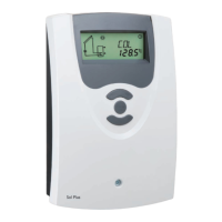
Sol Plus
Article/Artikel 7630422
Soft version 2.00
Serial number
IP 20
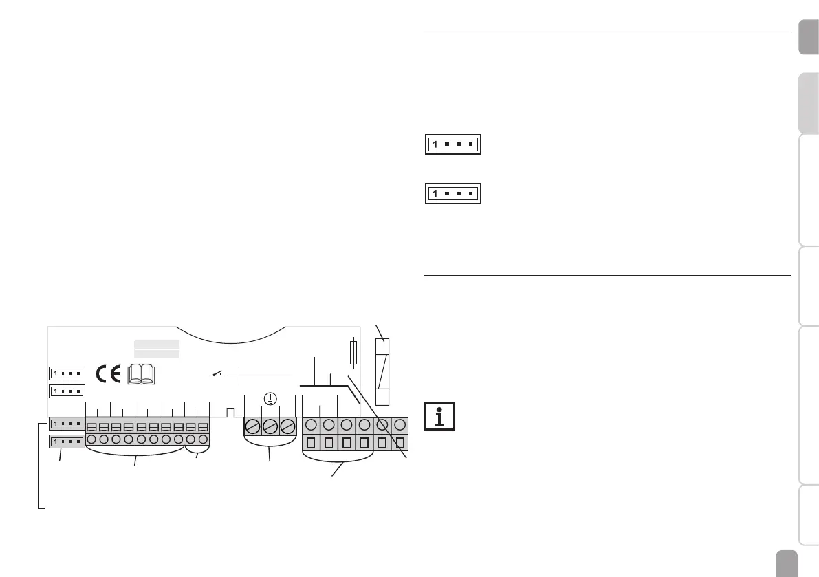
The power supply of the device must be 100 … 240 V~ (50 … 60 Hz). Attach exible
cables to the housing with the enclosed strain relief and the corresponding screws.
The controller is equipped with 2 semiconductor relays to which loads such as
pumps, valves, etc. can be connected:
Relay 1 Relay 2
18 = Conductor R1 16 = Conductor R2
17 = Neutral conductor N 15 = Neutral conductor N
13 = Protective earth conductorr ⏚ 14 = Protective earth conductorr ⏚
The mains connection is at the following terminals:
19 = Neutral conductor N
20 = Conductor L
12 = Protective earth conductor ⏚
Connect the temperature sensors (S1 to S4) to the corresponding terminals
with either polarity:
1 / 2 = Sensor 1 (e. g. collector sensor 1)
3 / 4 = Sensor 2 (e. g. store sensor 1)
5 / 6 = Sensor 3 (e. g. store sensor top)
7 / 8 = Sensor 4 (e. g. return sensor)
Fuse
VBus
®
ModBus
connection
PWM
connection
mains
terminals
load terminals
sensor terminals
protective earth
conductor terminal
2.3 PWM outputs
Speed control of a HE pump is possible via a PWM signal. The pump has to be con-
nected to the relay as well as to one of the PWM outputs of the controller. Power
is supplied to the HE pump by switching the corresponding relay on or off.
The terminals marked PWM 1 / 2 are control outputs for pumps with PWM con-
trol input.
2 4
1 3
1 (1) A 240 V~
1 (1) A 240 V~
R1
R2
LN
R1
N
2019
18
171615
14131212
NR2
T2A
100 ... 240 V~
50-60 Hz
Temp. Sensor Pt1000
S2S1 S3 S4 VBus
PWM 1/2
ModBus
3
4
5678910
F-67580 Mertzwiller
DDTh
Sol Plus
Article/Artikel 7630422
Soft version 2.00
Serial number
IP 20
1 = PWM output 1, control signal
2 = PWM output 1, GND
3 = PWM output 2, GND
4 = PWM output 2, control signal
2 4
1 3
1 (1) A 240 V~
1 (1) A 240 V~
R1
R2
LN
R1
N
2019
18
171615
14131212
NR2
T2A
100 ... 240 V~
50-60 Hz
Temp. Sensor Pt1000
S2S1 S3 S4 VBus
PWM 1/2
ModBus
3
4
5678910
F-67580 Mertzwiller
DDTh
Sol Plus
Article/Artikel 7630422
Soft version 2.00
Serial number
IP 20
1 = ModBus A
2 = GND
3 = free
4 = ModBus B
ModBus = Optional (for connection to the boiler (if provided by the boiler))
2.4 Data communication / Bus
The controller is equipped with the VBus
®
for data transfer and energy supply
to external modules. The connection is to be carried out at the terminals marked
VBus (either polarity).
One or more VBus
®
modules can be connected via this data bus, such as:
• DL2 Datalogger
• DL3 Datalogger
Furthermore, the controller can be connected to a PC or integrated into a network
via the VBus
®
/USB or VBus
®
/LAN interface adapter (not included).
Note
More accessories on page 69.