6 Electrical wiring
Fasten the remote control to a wall of the reference room.
The remote control must be freely accessible and must not be obstructed, free air circulation must be guar-
anteed.
A 3 / B 3
N EP 42A 52A
Sensor Inputs
DNG 61S
DNG 51S
43A
N EP 22A 3
2A
DNG R
DNG 41S
stuptuO eerF
laitnetoP
33A
3B 3A
DNG 31S
TMS I/O
23A
L N EP
`L N EP
`L N EP
N EP `L 01A
N EP 1A 1 L`
N EP `L 21A
N EP `L 41A
N EP 10A
N
EP 20A
N EP 30A
N EP 40A N EP 02A 1
2
A
rewoP
stuptuO rotautcA
ylppuS rotautcA
stu
ptuO r
ota
utcA
stuptuO rotautcA
DNG V5+ 52S
DNG
V5+ 62S
DNG V5+ 72S
DNG V5+ 82S
DNG V5+ 92S
Akt
u
ator Signa
l
DNG 04A
DNG 14A
DNG 24A
DNG 34A
DNG 44A
DNG 54A
DNG 64A
DNG SSn KLC OM IM
0T1 0T1
0T2 0T2
2B 2A
1B V21+ DNG 1A
14S 04S DNG V5+ 02S
34S 24S DNG V5+ 12S
54S 44S DNG V5+ 2
2S
74S 64S DNG V5+ 32S
94S 84S DNG V5+ 42S
DNG 10S
S
ensor Inputs
DNG 3
0
S
DNG 40S
DNG 5
0S
DNG 60S
DNG 70S
DNG 80S
DNG 90S
DNG 01S
1S DNG 1
DNG 21S
03A 03A
13A
DS
Fuse
54 JR
Sensor
Inputs
Sensor
Inputs
Sensor Inputs
A 3
B 3
230 V / 2~ / 50 Hz
A1
B
1
2
A2
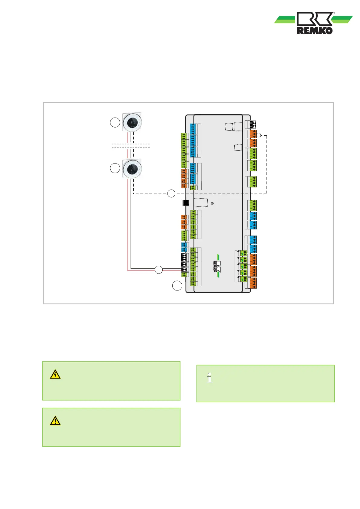
Fig. 5: Installation schematic with two remote controls
A1: Remote control 1 Easy-Control EC1
A2: Remote control 2 Easy-Control EC1
B: I/O module
1: Power supply 230V/2~/50Hz
2: Control line Easy-Control A3/B3
(e.g. 2 x 0.75 mm
2
screened)
A3 = red
B3 = white
DANGER!
All electrical installation work must be done by
an electrician.
WARNING!
All electric lines are in accordance VDE regula-
tions to dimension and to lay
.
One EC1 remote control is possible per heating
cycle.
15