42
REMKO GPM
N L
230V 50Hz
M1
VA1
VA2
N
L
PE
N
L
PE
LED
NTC
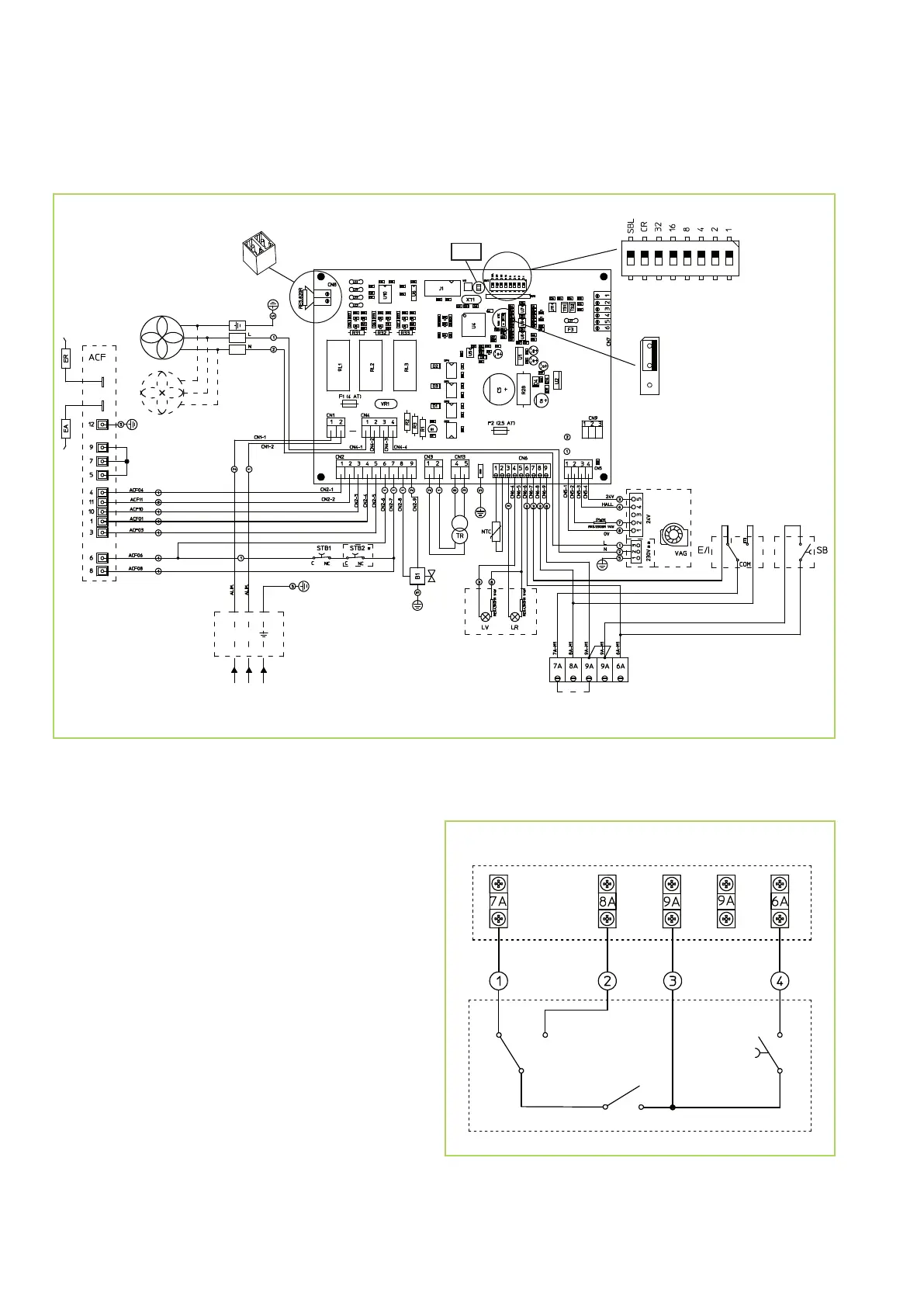
Electrical connection diagram
Legend:
ACF = Flame monitoring unit
B1 = Ignition burner solenoid valve
CN = Electronic temperature regulation connection
EA = Ignition electrode
ER = Ionisation electrode
E/I = Summer/winter toggle switch
F1 = Fuse 4A
F2 = Fuse 2.5A
LR = Fault lamp
LV = Operating lamp
M1 = Terminal block
NTC = Sensor NTC 1
SB = Fault clearing button
STB = Safety thermostat (resetting)
TR = Transformer 230/24V
VA1 = Fan
VA2 = Fan (only GPM 55/75)
VAG = Burner fan
We reserve the right to modify the dimensions and constructional design as part of the ongoing technical development process.
(ENTRIEGELUNG)
(WECHSELSCHALTER)
(SOMMER)
(WINTER)
(Ein / Aus)
Terminal block M1
CN
 Loading...