7
Condensate connection
and safe drainage
3
2
4
9
5 5
11
100
6
8
7
10 10
12 12
1
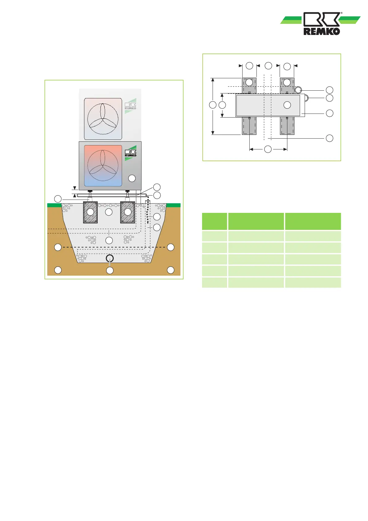
Fig. 43: Condensate drainage, seepage of conden-
sate and strip foundation (cross-section)
1: Outdoor unit
2: Leg
3: Condensate collection tray
4: Floor bracket
5: Reinforced strip foundation
HxWxD = 300x200x800mm
6: Gravel layer for seepage
7: Condensate drainage heating
8: Drainage channel
9: Conduit for refrigerant piping and electrical
connecting line (temperature-resistant up to at
least 60°C)
10: Frost line
11: Drainage pipe
12: Soil
Fig. 44: Dimensions for the strip foundation (bird's
eye view)
Please see the legend of Fig. 43 for the descrip-
tions of 1,3,5,8,9 and 11
Dimensions of the strip foundation (in mm)
Dimen-
sion
RVT 262-522 RVT 682
A 800 800
B 200 200
C 530 590
D 290 333
E 330 390
Condensate drainage connection
If the temperature falls below the dew point, con-
densation will form on the finned condenser during
heating mode.
A condensate tray should be installed on the
underside of the unit to drain any condensate.
n The condensate tray should have an incline of
min. 2%. This is the responsibility of the cus-
tomer. If necessary, fit vapour-diffusion-proof
insulation.
n When operating the unit at outside tempera-
tures below 4℃, ensure the condensate
drainage is laid to protect it against frost. The
lower part of the housing and condensate tray
is also to be kept frost free in order to ensure
permanent draining of the condensate. If nec-
essary, fit a pipe heater.
n Following installation, check that the conden-
sate run off is unobstructed and ensure that the
line is durably leak tight.
37